Typical BACnet EIA-485 Data Bus Transmission Example
Network Guide 129
APPENDIX A
Typical BACnet EIA-485 Data Bus
Transmission Example
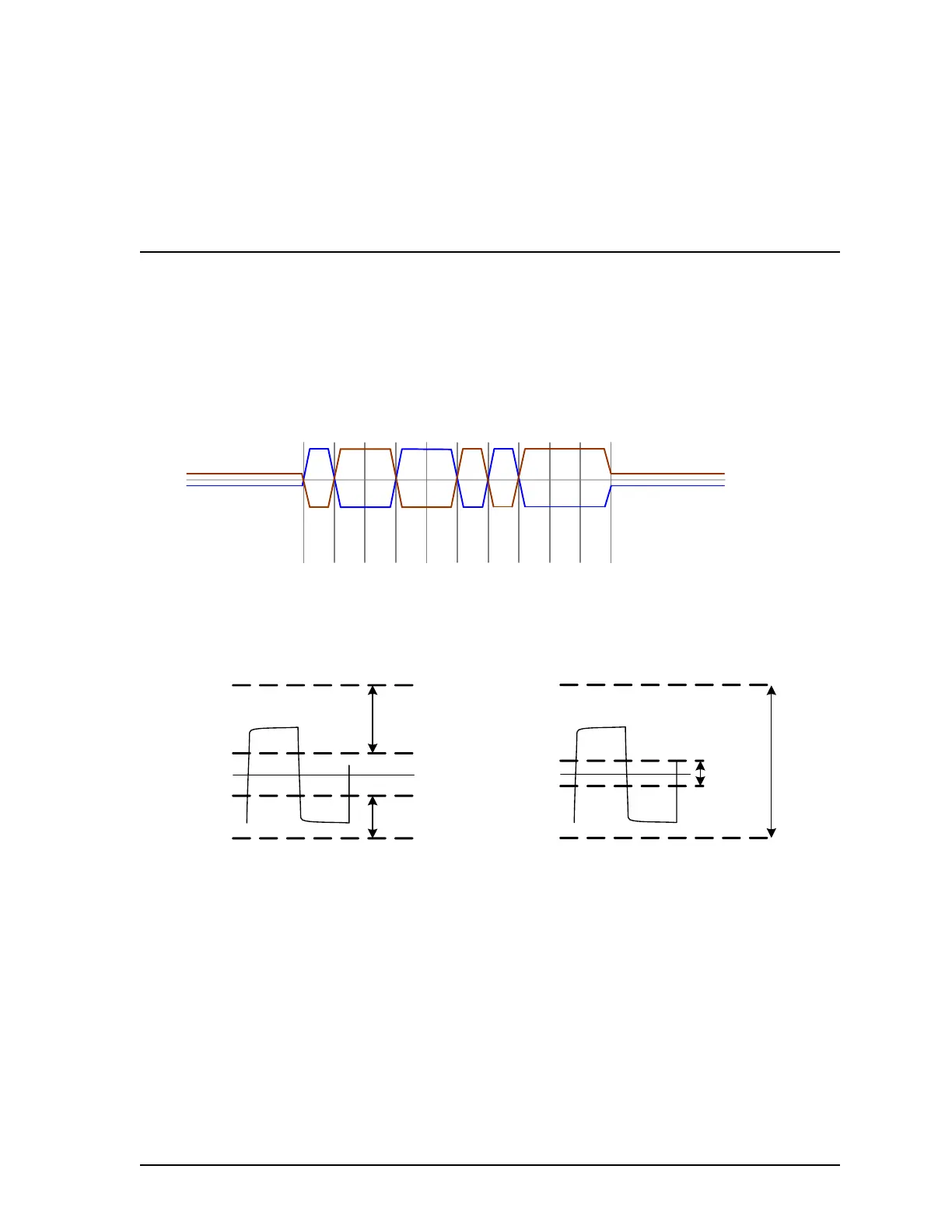
The graph below shows electrical signals for the transmission of one byte of data (hexadeci-
mal D3, least significant bit first). Note that when idle, the BACnet MS/TP data bus is biased
such that the Net + connection is positive with respect to the Net - connection.
Figure 72: Example of a Typical EIA-485 Data Bus Transmission
The permitted voltage levels of an EIA-485 transmitter and receiver are shown below.
Figure 73: Typical EIA-485 Data Bus Operating Signal Levels
Net -
Net +
Mark
Idle
Mark
Idle
Space Start
Stop
10100111
Mark Space
Mark
Space
Mark
+12 Volts
+2 Volts
-2 Volts
-7 Volts
Permissible
Range
Permissible
Range
Voltage V
Net-,Net+
EIA-485 Transmitter Signal Voltage
+12 Volts
+0.2 Volts
-0.2 Volts
-7 Volts
Maximum
Operating
Range
Transition
Region
Voltage V
Net-,Net+
EIA-485 Receiver Differential Input
 Loading...


