LonWorks Communication Bus Fundamentals
Network Guide 63
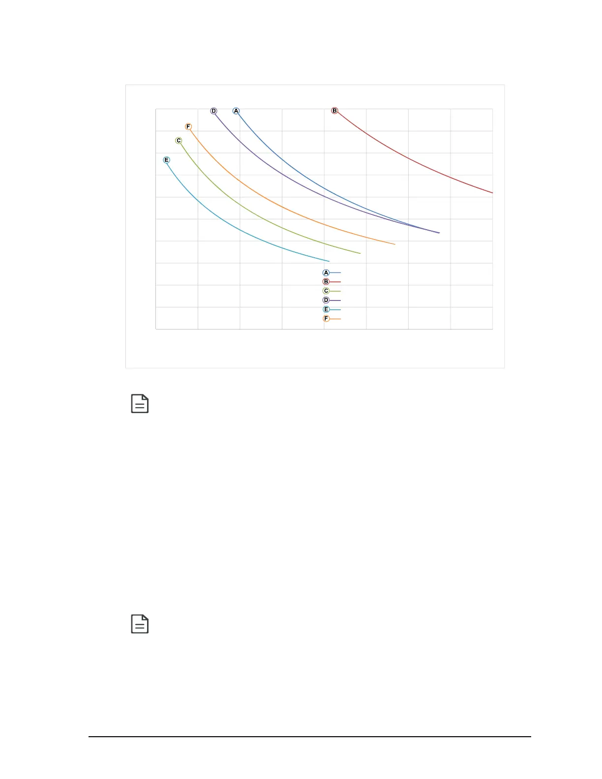
Figure 37: Maximum Number of VAVS Devices on a Daisy-Chain at Evenly Spaced Intervals
For non-VAV devices, determine the appropriate size transformer for the job as follows:
• Add up the power requirements of all devices plus all external loads (see About External
Loads on page 61). Multiply the total power needed by a multiplier of 1.3, as a security
margin. For example, to power five devices (15 VA each), the total load is 75 VA multiplied
by 1.3 is 98 VA. Choose a size of transformer just over this amount: For example, a 100
VA model.
• When the total load of a number of devices requires a transformer with a rating greater
than 100 VA, use two or more transformers. Ensure that the load to be connected to each
transformer follows the guideline of Step 1 above.
Laboratory testing conditions for the above graph are as follows:
• Distance between each VAV is evenly spaced along the entire wire length
• Transformer specification: 100VA (120/24VAC)
• Tested at room temperature with low voltage line conditions: 108VAC (50Hz)
Always use a separate transformer for each ECL-600 series controller and for each
of its associated I/O Extension Modules. One terminal on the secondary side of each
of these transformers must be connected to the building's ground and to the respec-
tive controller's or I/O Extension Modules' 24V COM terminal. See ECx-4XX I/O
Extension Module Power Supply Requirements on page 66.
0
1
2
3
4
5
6
7
8
9
10
100150200250300350400450500
MaxVAVSinDaisy‐Chain
TotalWireLength
DaisyChainPerformance
VAVS + SmartVue (AWG18)
VAVS + SmartVue (AWG16)
VAVS + SmartVue + 2DO (1,6VA each) (AWG18)
VAVS + SmartVue + 2DO (1,6VA each) (AWG16)
VAVS + SmartVue + SmartVue CO2 + 2DO (1,6VA each) (AWG18)
VAVS + SmartVue + SmartVue CO2 + 2DO (1,6VA each) (AWG16)
(30) (45) (60) (75) (90) (105) (120) (135) (150)
Feet
(meters)