5/12
Input Wiring
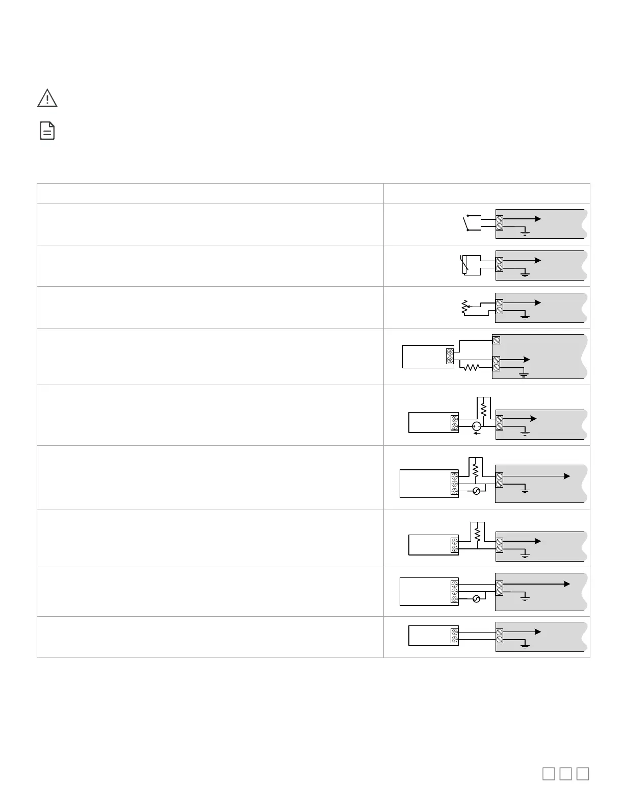
Table 2 shows the available universal input (UIx) wiring methods.
Before connecting a sensor to the controller, refer to the installation guide of the equipment manufacturer.
For a wire length less than 75’ (23m), either a shielded or unshielded 18AWG wire may be used.
- For a wire up to 200’ (61m) long, a shielded 18AWG wire is recommended.
- The shield of the wire should be grounded on the controller side only and the shield length should be kept as short as possible.
Table 2: Input Wiring
Dry Contact input.
UIx
COM
To Digital
Input
Digital Dry Contact
NO-NC
RTD input (for example, 1000Ω).
- Thermistor Input (for example, 10kΩ type II and III).
UIx
COM
To Analog-
To-Digital
Converter
RTD/
Thermistor
Resistive input, maximum 350kΩ (for example, use with 10kΩ and 100kΩ potentiometers).
UIx
COM
To Analog-
To-Digital
Converter
Potentiometer
10kΩ
0 to 20mA input used with a 2-wire, 0 to 20mA sensor powered by the
15VDC power supply.
+
–
Sensor
0-20mA
UIx
COM
+15VDC
To Controller’s
Analog-To-Digital
Converter
249Ω / ¼W
0 to 20mA input used with a 2-wire, 0 to 20mA sensor powered by
power supply.
-
+
0-20mA
Sensor
UIx
COM
To Analog-
To-Digital
Converter
24VDC
249Ω ¼W
0 to 20mA input used with a 3-wire, 0 to 20mA sensor powered by
power supply.
AC
+
Common
0-20mA
Sensor
UIx
COM
To Analog-
To-Digital
Converter
24VAC
249Ω ¼W
0 to 20mA input used with a sensor powered by its own power source.
+
-
0-20mA
Sensor
UIx
COM
To Analog-
To-Digital
Converter
249Ω ¼W
Voltage input used with a 3-wire 0 to 10VDC or 0 to 5VDC sensor powered by
24 AC/DC power supply.
AC
+
Common
0-10V
Sensor
UIx
COM
To Analog-
To-Digital
Converter
24VAC
Voltage input used with a 0 to 10VDC or 0 to 5VDC sensor
source.
+
-
0-10V
Sensor
UIx
COM
To Analog-
To-Digital
Converter
 Loading...