Programming and status display instructions
1. Status display
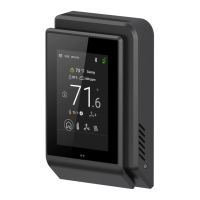
The thermostat features a two-line, eight-character display. There is a low level back-light level that is always active and can only be
seen at night. When left unattended, the thermostat has an auto scrolling display that shows the actual status of the system. Each
item is scrolled one by one with the back lighting off. Pressing any key will cause the back light to come on.
Sequence of auto-scroll status display:
Clock status
System mode
Schedule status
Alarms
Frost ON
SetClock
Filter
Sys mode emergenc
Fan lock
Manual scroll of each menu item is achieved by pressing the Yes ( scroll ) key repetitively. The last item viewed will be shown on the
display for 30 seconds before returning to automatic scrolling. Temperature is automatically updated when scrolling is held.
Outdoor air temperature display is only enabled when an outdoor air temperature sensor is connected.
• A maximum range status display of 50 °C ( 122 °F ) indicates a shorted sensor. Associated functions, such as mode lockouts and
economizer function are automatically disabled.
• A minimum range status -40 °C ( -40 °F ) is not displayed and indicates an opened sensor or a sensor not connected. Associated
functions, such as mode lockouts and economizer function are automatically disabled.
If alarms are detected, they will automatically be displayed at the end of the status display scroll. During an alarm message display,
the back lit screen will light up at the same time as the message and shut off during the rest of the status display. Two alarms
maximum can appear at any given time. The priority for the alarms is as follows:
Indicates that the heating is energized by the low limit frost protection room temperature setpoint 5.6 °C ( 42 °F )
Indicates that the clock needs to be reset. There has been a power failure which has lasted longer than 6 hours
Indicates that there is a service alarm as per one of the programmable digital input ( DI1 or DI2 )
Indicates that the filters are dirty as per one of the programmable digital input ( DI1 or DI2 )
Indicates that the heating and cooling action are locked out due to a defective fan operation
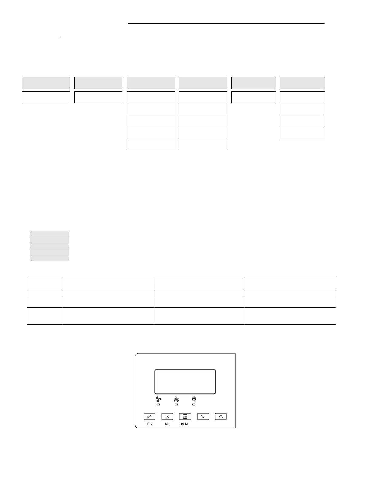
Three status LEDs on the thermostat cover are used to indicate the status of the fan, a call for heat, or a call for cooling.
Heatpump models CDIVI-76xxH
Multistage and single stage models
CDIVI-7652A & CDIVI-7652B
Multistage economizer models
CDIVI-7656B
When G Fan terminal operates
When G Fan terminal operates
When G Fan terminal operates
When Y1 and / or W1 terminal(s)
operate in heating mode
When W1 terminal operate in heating
mode
When W1 terminal operate in heating
mode
on
When Y1 terminal operate in cooling
mode
When Y1 terminal operate in cooling
mode
When Y1 terminal operate in cooling
mode and or economizer output is in
Fig.10 – Heatpump, multistage and single stage models