11
WEL - IP1891
GB
1. TECHNICAL DETAILS
WELM WELS WELE
Power supply 230 V~ / 50-60 Hz 230 V~ / 50-60 Hz 230 V~ / 50-60 Hz
Absorption 1A 1A 1A
Maximum torque 50 Nm 30 Nm (opening)
20 Nm (closing)
30 Nm (opening)
20 Nm (closing)
Intermittence S2 = 30 min, S3 = 80 % S2 = 30 min, S3 = 80 % S2 = 30 min, S3 = 80 %
Opening time 1,5÷5 s / 90° 1,5÷5 s / 90° 2÷10 s / 90°
Closing time 1,5÷5 s / 90° 1,5÷5 s / 90° 3÷8 s / 90°
Operation type Motor opening
Motor closing
Motor opening
Spring closing
Motor opening
Spring closing
Accessories power supply 24 V= / 0,5 A 24 V= / 0,5 A 24 V= / 0,5 A
Temperature
-20°C / +55°C
(Batteries +5°C / +40°C)
-20°C / +55°C
(Batteries +5°C / +40°C)
-20°C / +55°C
(Batteries +5°C / +40°C)
Degree of protection IP31 IP31 IP31
Control panel 99 99 + BRAKE EL12E
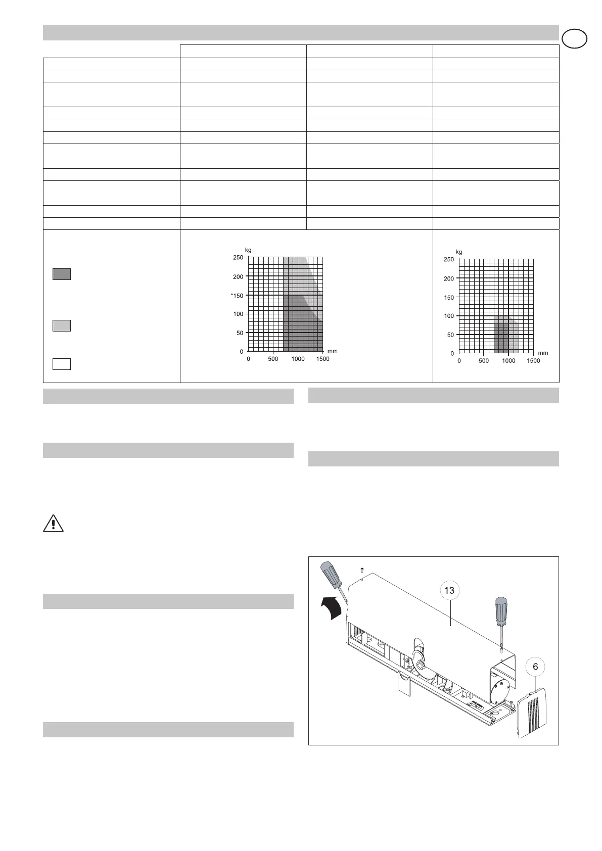
Applications:
mm = door wing width
kg = door wing weight
Recommended
dimensions
for heavy duty use
(600 cycles/day)
Limit dimensions for
intensive use
(100÷200 cycles/day)
Unauthorised usage
2. REFERENCE TO ILLUSTRATION
The given operating and performance features can only be gua-
ranteed with the use of DITEC accessories and safety devices.
2.1
Standard installation references
(fig. 1)
[1] Automation WEL
[2] Radar
[3] Sliding arm
[4] Connect power supply to a type-approved omnipolar
switch with a contact opening gap of no less that 3 mm
(not supplied by us) protected against accidental and
unauthorized activation. Connection to supply mains must
be carried out in an independent raceway separate from
control connections and safety device connections.
[5] Stop
2.2 Automation references (fig. 2)
[6] Heads
[7] Control panel
[8] Gearmotor
[9] Base plate
[10] Brake card (WELS only)
[11] Spring (WELS and WELE only)
[12] Limit switch
[13] Casing
3. INSTALLATION
Unless otherwise specified, all measurements are expressed
in millimetres (mm).
3.1 Preliminary checks
Check stability, the weight of the door and that movement is
smooth and free of friction (if necessary strengthen the frame).
Any door closers must be removed or completely cancelled.
3.2 Automation dismantling
Open the casing [13] by placing a screwdriver in the appropriate
slot on the heads.
Remove the heads [6], detach the connectors of the power con-
nections and the fixing brackets and take out the control panel
[7], the gearmotor [8] and the BRAKE card [10] (if fitted).
Attention: do not remove or move the brackets in the base plate
guides.
Attention: carefully handle the control panel, as indicated in figure.
At the end of the automation dismantling phase proceed with the
installation phases indicated in chapters 4, 5 or 6, depending on
the type of arm used.
*Warning: in case of
doors with two doors
without overlap, the
weight if each door
should not exceed 150
kg.