dIXEL
Installing and Operating Instructions
1592026000
1592026000 XW20K GB R1.0 22.02.2008.doc XW20K 4/5
fins in the coldest place, where most ice is formed, far from heaters or from the warmest place during
defrost, to prevent premature defrost termination.
10. TTL/RS485 Serial line
The TTL connector allows, by means of the external module TTL/RS485 (XJ485CX), to connect the
unit to a network line ModBUS-RTU compatible as the dIXEL monitoring system XJ500 (Version
3.0). The same TTL connector is used to upload and download the parameter list of the “HOT KEY“.
The instruments can be ordered wit the serial output RS485(Optional).
11. Use of the programming “HOT KEY “
The Wing units can UPLOAD or DOWNLOAD the parameter list from its own E2 internal memory to
the “Hot Key” and vice-versa.
11.1 DOWNLOAD (FROM THE “HOT KEY” TO THE INSTRUMENT)
1. Turn OFF the instrument by means of the ON/OFF key, remove the TTL serial cable if present,
insert the “Hot Key” and then turn the Wing ON.
2. Automatically the parameter list of the “Hot Key” is downloaded into the Wing memory, the
“DoL” message is blinking. After 10 seconds the instrument will restart working with the new
parameters.
3. Turn OFF the instrument remove the “Hot Key”, plug in the TTL serial cable, then turn it ON
again.
At the end of the data transfer phase the instrument displays the following messages:
“end “ for right programming.
The instrument starts regularly with the new programming.
“err” for failed programming.
In this case turn the unit off and then on if you want to restart the download again or remove
the “Hot key” to abort the operation.
11.2 UPLOAD (FROM THE INSTRUMENT TO THE “HOT KEY”)
1. Turn OFF the instrument by means of the ON/OFF key and remove the TTL serial cable if
present; then turn it ON again.
2. When the Wing unit is ON, insert the “Hot key” and push
o key; the "uPL" message
appears.
3. Push “SET” key to start the UPLOAD; the “uPL” message is blinking.
4. Turn OFF the instrument remove the “Hot Key”, plug in the TTL serial cable, then turn it ON
again.
At the end of the data transfer phase the instrument displays the following messages:
“end “ for right programming.
“err” for failed programming. In this case push “SET” key if you want to restart the
programming again or remove the not programmed “Hot key”.
12. ALARM SIGNALS
Message Cause Outputs
“P1” Thermostat probe failure
larm output ON; Compressor output according to
parameters “COn” and “COF”
“P3” Probe 3 probe failure Alarm output ON; Other outputs unchanged
“P4” Probe 4 probe failure Alarm output ON; Other outputs unchanged
“HA” Maximum temperature alarm Alarm output ON; Other outputs unchanged
“LA” Minimum temperature alarm Alarm output ON; Other outputs unchanged
"HA2" Condenser high temperature It depends on the “Ac2” parameter
"LA2" Condenser low temperature It depends on the “bLL” parameter
“dA” Door open Compressor and fans restarts
“EA” External alarm Output unchanged.
“CA” Serious external alarm (i1F=bAL) All outputs OFF.
“CA” Pressure switch alarm (i1F=PAL) All outputs OFF
“EE” Data or memory failure Alarm output ON; Other outputs unchanged
The alarm message is displayed until the alarm condition is recovery.
All the alarm messages are showed alternating with the room temperature except for the “P1” which is
flashing.
To reset the “EE” alarm and restart the normal functioning press any key, the “rSt” message is
displayed for about 3s.
12.1 SILENCING BUZZER
Once the alarm signal is detected the buzzer can be silenced by pressing any key. Buzzer is mounted
in the keyboard and it is an option.
12.2 “EE” ALARM
The dIXEL instruments are provided with an internal check for the data integrity. Alarm “EE” flashes
when a failure in the memory data occurs. In such cases the alarm output is enabled.
12.3 ALARM RECOVERY
Probe alarms : “P1” (probe1 faulty), “P3” and “P4”; they automatically stop 10s after the probe restarts
normal operation. Check connections before replacing the probe.
Temperature alarms “HA”, “LA” “HA2” and “LA2” automatically stop as soon as the temperature
returns to normal values.
Alarms “EA” and “CA” (with i1F=bAL) recover as soon as the digital input is disabled.
Alarm “CA” (with i1F=PAL) recovers only by switching off and on the instrument.
13. Technical data
Keyboards
Housing: self extinguishing ABS.
Case: T620: facia 38x185 mm; depth 23mm
V620: facia 72x56 mm; depth 23mm
CX620: facia 75x36 mm; depth 23mm
Mounting: T620: panel mounting in a 150x31 mm panel cut-out with two screws.
∅ 3 x 2mm.
Distance between the holes 165mm
V620: panel mounting in a 56x72 mm panel cut-out with two screws.
∅ 3x2mm. Distance
between the holes 40mm
CX620: panel mounting in a 71x29mm panel cut-out
Protection: IP20; Frontal protection: IP65 with frontal gasket
Connections: Screw terminal block
≤ 2,5 mm
2
Power supply: from XW20K power module
Display: 3 digits, red LED, 14,2 mm high.
Optional output: buzzer
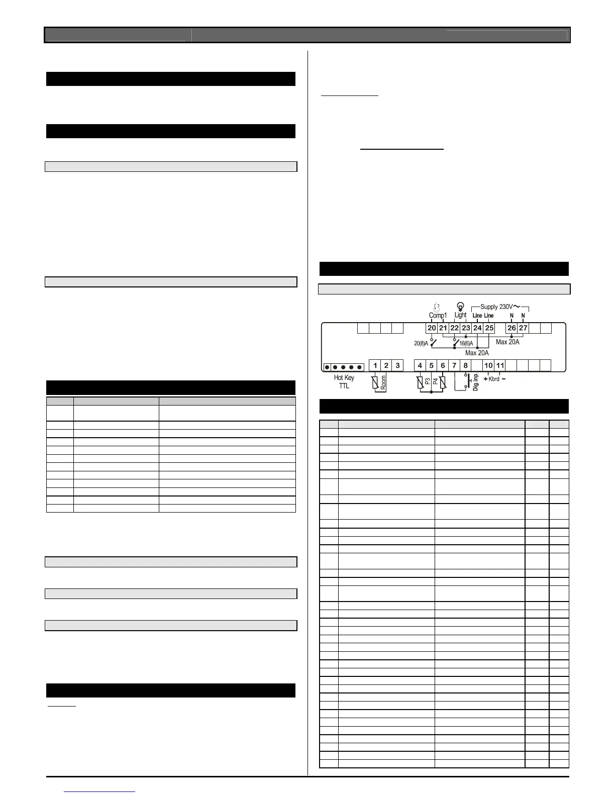
Power module XW20K
Case: 8 DN: 140X176X148.
Connections: Screw terminal block
≤ 2,5 mm
2
heat-resistant wiring and 6,3mm Faston
Power supply: 230Vac or. 110Vac ± 10% or 24Vac
Power absorption: 10VA max.
Inputs: 4 NTC probes
Digital inputs: 1 free voltage
Relay outputs: Total current on loads MAX. 20A
compressor: relay SPST 20(8) A, 250Vac
light (oA3): relay SPST 16(5) A, 250Vac
Serial output : TTL standard.
Communication protocol: Modbus - RTU
Data storing: on the non-volatile memory (EEPROM).
Kind of action: 1B.
Pollution grade: normal
Software class: A.
Operating temperature: 0÷60 °C.
Storage temperature: -25÷60 °C.
Relative humidity: 20
÷85% (no condensing)
Measuring and regulation range: NTC probe: -40÷110°C (-58÷230°F)
Resolution: 0,1 °C or 1°C or 1 °F (selectable).
Accuracy (ambient temp. 25°C): ±0,5 °C ±1 digit
14. CONNECTIONS
14.1 XW20K
15. Default setting values
Label Name Range Default Level
REGULATION
Set Set point LS÷US
3.0 - - -
Hy Differential 0,1÷25,5 °C / 1÷45°F
2.0 Pr1
LS Minimum set point -50,0°C÷SET / -58°F÷SET
-50.0 Pr2
US Maximum set point SET ÷ 110°C / SET ÷ 230°F
110 Pr2
Ot Thermostat probe calibration
-12÷12°C /-120÷120°F
0.0 Pr1
P3P Third probe presence (1st cond.
probe)
n=not present; Y=pres.
n Pr2
O3 Third probe calibration
-12÷12°C /-120÷120°F
0 Pr2
P4P Fourth probe presence (2nd cond.
probe)
n=not present; Y=pres.
n Pr2
O4 Fourth probe calibration
-12÷12°C /-120÷120°F
0 Pr2
OdS Outputs activation delay at start up 0÷255 min.
0 Pr2
AC Anti-short cycle delay 0÷30 min.
1 Pr1
Ac1 Second compressor delay 0÷255s
5 Pr2
CCt Compressor ON time during fast
freezing
0 ÷ 23h 50 min.
0.0 Pr2
CCS Set point for continuous cycle (-55.0÷150,0°C)
3 Pr2
COn Compressor ON time with faulty probe 0÷255 min.
15 Pr2
COF Compressor OFF time with faulty
probe
0÷255 min.
30 Pr2
CH Kind of action CL=cooling; Ht= heating
cL Pr1
DISPLAY
CF Temperature measurement unit °C ÷ °F
°C Pr2
rES Resolution (integer/decimal point) in ÷ de
dE Pr1
rEd Remote display P1 ÷ 1r2
P1 Pr2
dLy Display temperature delay 0 ÷ 20.0 min (10 sec.)
0 Pr2
DEFROST
dFP Probe selection for defrost termination nP; P1; P2; P3; P4
nP Pr2
dtE Defrost termination temperature -50,0÷110°C / -58÷230°F
0 Pr2
IdF Interval between defrost cycles 1÷120h
8 Pr1
MdF (Maximum) length for 1° defrost 0÷255 min.
20 Pr1
dFd Displaying during defrost rt, it, SEt, dEF, dEG
it Pr2
dAd MAX display delay after defrost 0÷255 min.
30 Pr2
AUXILIARY THERMOSTAT
ACH Kind of action for auxiliary relay CL; Ht
cL Pr2
SAA Set Point for auxiliary relay -50,0÷110°C / -58÷230°F
0,0 Pr2
SHy Differential for auxiliary relay 0,1÷25,5 °C / 1÷45°F
2,0 Pr2
ArP Probe selection for auxiliary relay nP / P1 / P2 / P3
nP Pr2
Sdd Aux.output working during defrost n, y
n Pr2
ALARMS
 Loading...