1592009760 XW60VS GB Rel 1.1 .09.11.2011 XW60VS 3/4
6.4 PRESSURE SWITCH (I2F = PAL)
If during the interval time set by “did” parameter, the pressure switch has reached the number of activation of the
“nPS” parameter, the “PAL” pressure alarm message will be displayed. The compressor and the regulation are
stopped. When the digital input is ON the compressor is always OFF.
If the nPS activation in the did time is reached, switch off and on the instrument to restart normal
regulation.
6.5 START DEFROST (I2F = DFR)
It executes a defrost if there are the right conditions. After the defrost is finished, the normal regulation will restart
only if the digital input is disabled otherwise the instrument will wait until the “Mdf” safety time is expired.
6.6 ENERGY SAVING (I2F = ES)
The Energy Saving function allows to change the set point value as the result of the SET+ HES (parmeter) sum.
This function is enabled until the digital input is activated.
6.7 REMOTE ON/OFF (I2F = ONF)
This function allows to switch ON and OFF the instrument.
6.8 DIGITAL INPUTS POLARITY
The digital input polarity depends on the “I2P” parameters.
CL : the digital input is activated by closing the contact.
OP : the digital input is activated by opening the contact
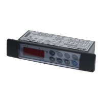
7. INSTALLATION AND MOUNTING
Instruments XW60VS shall be mounted on vertical panel, in a 72x56 mm hole, and fixed using screws 3 x 2mm.
To obtain an IP65 protection grade use the front panel rubber gasket (mod. RGW-V).
The temperature range allowed for correct operation is 0 - 60 °C (32÷120°F). Avoid places subject to strong
vibrations, corrosive gases, excessive dirt or humidity. The same recommendations apply to probes. Let the air
circulate by the cooling holes.
7.1 XW60VS: CUT OUT
56
7
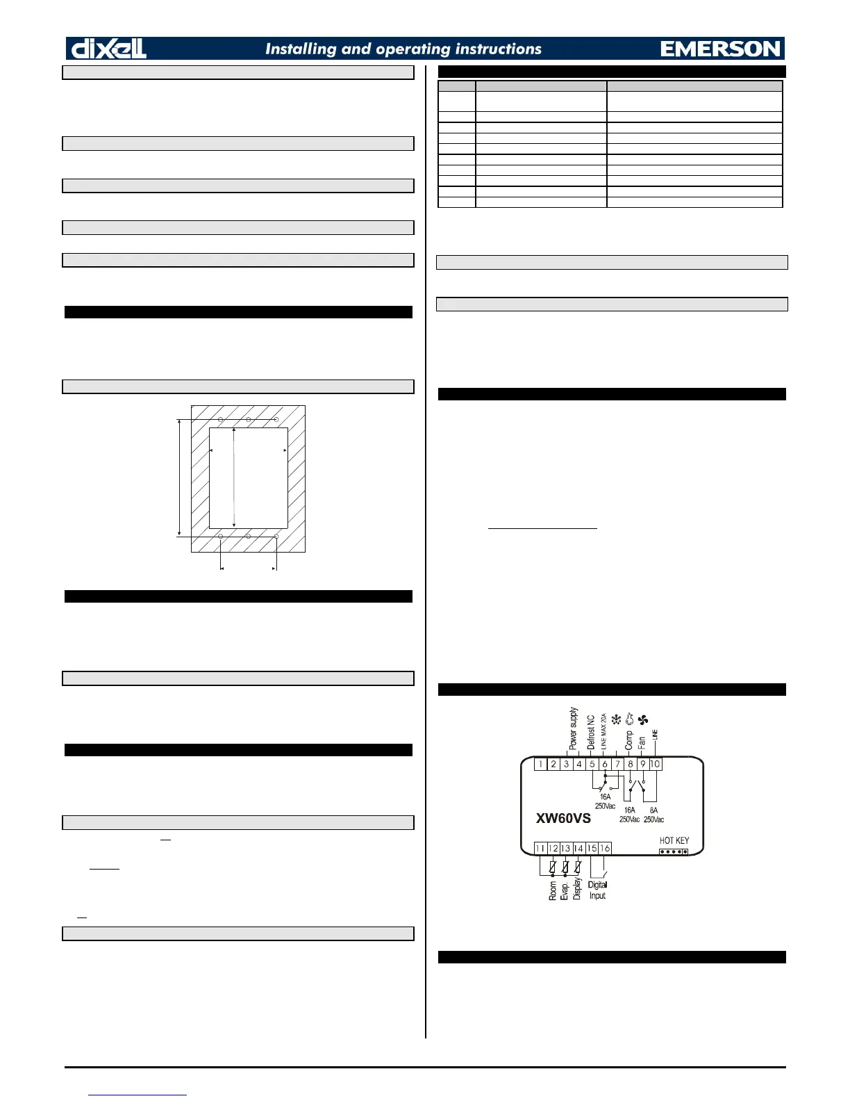
8. ELECTRICAL CONNECTIONS
The instrument is provided with faston connections (6,3mm). Heat-resistant cables have to be used. Before
connecting cables make sure the power supply complies with the instrument’s requirements. Separate the probe
cables from the power supply cables, from the outputs and the power connections. Do not exceed the maximum
current allowed on each relay, in case of heavier loads use a suitable external relay.
N.B. Maximum current allowed for all the loads is 20A.
8.1 PROBE CONNECTIONS
The probes shall be mounted with the bulb upwards to prevent damages due to casual liquid infiltration. It is
recommended to place the thermostat probe away from air streams to correctly measure the average room
temperature. Place the defrost termination probe among the evaporator fins in the coldest place, where most ice is
formed, far from heaters or from the warmest place during defrost, to prevent premature defrost termination.
9. USE OF THE PROGRAMMING “HOT KEY “
The XW60VS unit can UPLOAD or DOWNLOAD the parameter list from its own E2 internal memory to the “Hot
Key” and vice-versa.
Note: You must first program one controller with the front keypad. Double check the parameters that you want to
duplicate. Label the HOT KEY with a code for that program.
9.1 UPLOAD (FROM THE INSTRUMENT TO THE “HOT KEY”)
1. When the Controller is ON, insert the “Hot key” and push UP key; the "uPL" message appears followed
a by flashing “End”
2. Push “SET” key and the End will stop flashing;
3. Turn OFF the instrument remove the “Hot Key”, then turn it ON again.
(At the end of the data transfer phase the instrument displays the following messages:)
“End “ for right programming.
“Err” for failed programming. In this case push “SET” key if you want to restart the programming again or remove
the not programmed “Hot key”.
9.2 DOWNLOAD (FROM THE “HOT KEY” TO THE INSTRUMENT)
1. Turn OFF the instrument by means of the ON/OFF key (or un-plug the appliance), insert the “Hot Key” into
the 5 PIN receptacle and then turn the Controller ON.
2. Automatically the parameter list of the “Hot Key” is downloaded into the Controller memory, the “DoL”
message is blinking. After 10 seconds the instrument will restart working with the new parameters.
3. Turn OFF the instrument remove the “Hot Key”, then turn it ON again.
At the end of the data transfer phase the instrument displays the following messages:
“End “ for right programming. The instrument starts regularly with the new programming.
“Err” for failed programming. In this case turn the unit off and then on if you want to restart the download again or
remove the “Hot key” to abort the operation.
10. ALARM SIGNALS
Message Cause Outputs
“P1” Thermostat probe failure
Alarm output ON; Compressor output according to
parameters “COn” and “COF”
“P2” Evaporator probe failure Alarm output ON; Other outputs unchanged
“P3” Display probe failure Alarm output ON; Other outputs unchanged
“HA” Maximum temperature alarm Alarm output ON; Other outputs unchanged
“LA” Minimum temperature alarm Alarm output ON; Other outputs unchanged
“EE” Data or memory failure Alarm output ON; Other outputs unchanged
“dA” Door switch alarm Alarm output ON; Other outputs unchanged
“EAL” External alarm Alarm output ON; Other outputs unchanged
“bAL” Serious external alarm Alarm output ON; Other outputs OFF
“PAL” Pressure switch alarm Alarm output ON; Other outputs OFF
The alarm message is displayed until the alarm condition is recovery.
All the alarm messages are showed alternating with the room temperature except for the “P1” which is flashing. To
reset the “EE” alarm and restart the normal functioning press any key, the “rSt” message is displayed for about 3s.
10.1 “EE” ALARM
The dIXEL instruments are provided with an internal check for the data integrity. Alarm “EE” flashes when a
failure in the memory data occurs. In such cases the alarm output is enabled.
10.2 ALARM RECOVERY
Probe alarms : “P1” (probe1 faulty), “P2” and “P3”; they automatically stop 10s after the probe restarts normal
operation. Check connections before replacing the probe.
Temperature alarms “HA” and “LA” automatically stop as soon as the thermostat temperature returns to normal
values or when the defrost starts.
Door switch alarm “dA” stop as soon as the door is closed.
External alarms “EAL”, “BAL” stop as soon as the external digital input is disabled
Pressure switch alarm “PAL” alarm is recovered by switching OFF the instrument.
11. TECHNICAL DATA
Housing: self extinguishing ABS.
Case: facia 100x64 mm; depth 40mm
Mounting : panel mounting in a 56x72 mm panel cut-out with two screws. 3x2mm. Distance between the holes
40mm
Protection: IP20.
Frontal protection: IP65 with optional frontal gasket; RGW-V (XW60VS).
Connections: heat-resistant wiring and 6,3mm Faston for loads and power supply
Power supply: 230Vac 10% or 120Vac or 24Vac
Power absorption: 3VA max.
Display: 3 digits, red LED, 14,2 mm high.
Inputs: 3 NTC or PTC probes
Digital input: 1 free voltage
Relay outputs: Total current on loads MAX. 10A
compressor: relay SPST 16(6) A, 250Vac
fans: relay SPST 8(3) A, 250Vac
defrost: relay SPDT 16(6) A, 250Vac
Data storing: on the non-volatile memory (EEPROM).
Kind of action: 1B.
Pollution grade: normal
Software class: A.
Operating temperature: 0÷60 °C.
Storage temperature: -25÷60 °C.
Relative humidity: 2085% (no condensing)
Measuring and regulation range:
PTC probe: -50÷150°C (-58÷302°F)
NTC probe: -40÷110°C (-58÷230°F)
Resolution: 0,1 °C or 1°C or 1 °F (selectable).
Accuracy (ambient temp. 25°C): ±0,5 °C ±1 digit
12. CONNECTIONS
Power supply: use terminal 3-4; according to the model 230Vac or 120Vac or 24Vac
 Loading...