1592026020 XW60K GB R2.1 22.06.2012.doc XW60K 1/6
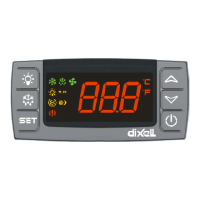
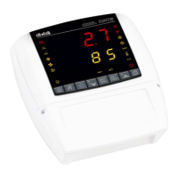
XW60K AND T620T - T620 – V620 – CX620
1 GENERAL WARNING ......................................................................................................... 1
2 GENERAL DESCRIPTION .................................................................................................. 1
3 CONTROLLING LOADS ...................................................................................................... 1
4 SPECIAL FUNCTIONS........................................................................................................ 1
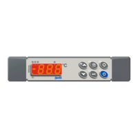
5 KEYBOARDS...................................................................................................................... 1
6 AUTOMATIC KEYBOARD LOCK (ONLY FOR T620T) ......................................................... 2
7 CONTROLLER INTERFACE ............................................................................................... 2
8 PARAMETER LIST ............................................................................................................. 3
9 DIGITAL INPUT .................................................................................................................. 4
10 INSTALLATION AND MOUNTING ....................................................................................... 4
11 ELECTRICAL CONNECTIONS............................................................................................ 5
12 TTL/RS485 SERIAL LINE .................................................................................................... 5
13 HOW TO: USE OF THE PROGRAMMING “HOT KEY” ......................................................... 5
14 ALARM SIGNALS ............................................................................................................... 5
15 TECHNICAL DATA ............................................................................................................. 5
16 CONNECTIONS.................................................................................................................. 5
17 DEFAULT SETTING VALUES ............................................................................................. 5
1 GENERAL WARNING
1.1 PLEASE READ BEFORE USING THIS MANUAL
This manual is part of the product and should be kept near the instrument for easy and quick
reference.
The instrument shall not be used for purposes different from those described hereunder. It
cannot be used as a safety device.
Check the application limits before proceeding.
Dixell Srl reserves the right to change the composition of its products, even without notice, ensuring the
same and unchanged functionality.
1.2 SAFETY PRECAUTIONS
Check the supply voltage is correct before connecting the instrument.
Do not expose to water or moisture: use the controller only within the operating limits avoiding
sudden temperature changes with high atmospheric humidity to prevent formation of
condensation
Warning: disconnect all electrical connections before any kind of maintenance.
Fit the probe where it is not accessible by the End User. The instrument must not be opened.
In case of failure or faulty operation send the instrument back to the distributor or to “Dixell S.r.l.”
(see address) with a detailed description of the fault.
Consider the maximum current which can be applied to each relay (see Technical Data).
Ensure that the wires for probes, loads and the power supply are separated and far enough from
each other, without crossing or intertwining.
In case of applications in industrial environments, the use of mains filters (our mod. FT1) in
parallel with inductive loads could be useful.
Dixell Srl reserves the right to change the composition of its products, even without notice,
ensuring the same and unchanged functionality.
2 GENERAL DESCRIPTION
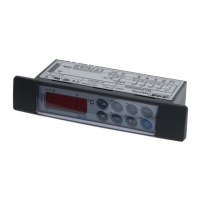
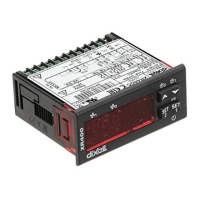
Model XW60K is microprocessor based controller suitable for applications on medium or low
temperature refrigerating units. It has to be connected by means of a two-wire cable ( 1mm) at a
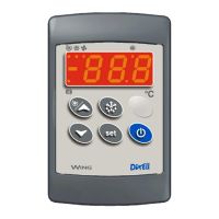
distance of up to 30 meters to the keyboard T620T or T620 or V620 or CX620. It is provided with four
relay outputs to control compressor, defrost - which can be either electrical or hot gas - the evaporator
fans and light. It is also provided with 4 NTC or PTC probe inputs, one for temperature control, one to
control the defrost end temperature of the evaporator and the third and fourth to control condenser
temperature or to display another temperature.
The HOT KEY output allows to connect the unit, by means of the external module XJ485-CX, to a
network line ModBUS-RTU compatible such as the dIXEL monitoring units of X-WEB family. It
allows to program the controller by means the HOT KEY programming keyboard.
The instrument is fully configurable through special parameters that can be easily programmed
through the keyboard.
3 CONTROLLING LOADS
3.1 THE COMPRESSOR
The regulation is performed according to the temperature measured by the thermostat probe with a
positive differential from the set point: if the temperature increases and reaches set point plus
differential the compressor is started and then turned off when the temperature reaches the set point
value again.
In case of fault in the thermostat probe the start and stop of the compressor are timed through
parameters Con and CoF.
The relay of the second compressor is activated in parallel with the relay of the first compressor, with a
possible delay set in the AC1 parameter. Both the compressors are switched off at the same time.
3.2 FAST FREEZING
When defrost is not in progress, it can be activated by holding the UP key pressed for about 3 sec.
The compressor operates to maintain the CCS set point for the time set through the CCt parameter.
The cycle can be terminated before the end of the set time using the same activation key UP for 3 sec.
3.3 DEFROST
Two defrost modes are available through the tdF parameter: defrost through electrical heater (tdF =
EL) and hot gas defrost (tdF = in).
The defrost interval depends on the presence of the RTC (optional). If the RTC is present is controlled
by means of parameter EdF:
- EdF=in: a defrost starts after elapsing the idF time (standard way for controller without RTC).
EdF=rtC: defrosts are scheduled by using a real time clock system, depending on the hours set in the
parameters Ld1..Ld6, during workdays, and in Sd1…Sd6 during holidays.
Other parameters are used to control defrost cycles: its maximum length (MdF) and two defrost
modes: timed or controlled by the evaporator’s probe (P2P).
At the end of defrost dripping time is started, its length is set in the Fdt parameter. With Fdt=0 the
dripping time is disabled.
3.4 CONTROL OF EVAPORATOR FANS
The fan control mode is selected by means of the FnC parameter:
FnC = C_n: fans will switch ON and OFF with the compressor and not run during defrost;
FnC = o_n fans will run even if the compressor is off, and not run during defrost;
After defrost, there is a timed fan delay allowing for drip time, set by means of the Fnd parameter.
FnC = C_Y fans will switch ON and OFF with the compressor and run during defrost;
FnC = o_Y fans will run continuously also during defrost.
An additional parameter FSt provides the setting of temperature, detected by the evaporator probe,
above which the fans are always OFF. This is used to make sure circulation of air only if his
temperature is lower than set in FSt.
3.4.1 Forced activation for fans
This function, managed by the FCt parameter, is designed to avoid short cycles of fans, that could
happen when the controller is switched on or after a defrost, when the room air warms the evaporator.
If the difference between the evaporator temperature and the room temperature is higher than the FCt
value, the controller will activate the fans. This function is disabled if FCt=0.
3.4.2 Timed activation of the fans when the compressor is off.
When FnC=C-n or C-Y (fans in parallel to the compressor), the fans will be able to carry out on and off
cycles even if the compressor is switched off. The on and off interval of time follow the Fon and FoF
parameters. When the compressor is stopped the fans will go on working for the Fon time. On the
other side, with Fon=0 the fans will stay always off when the compressor is off.
4 SPECIAL FUNCTIONS
By means of the parameter oA3, it’s possible to configure the functions of the light relay (22-23), as
described in the following paragraphs:
4.1 LIGHT RELAY (FACTORY SETTING, OA3 = LIG)
By setting oA3=Lig the relay will work as light relay, it is switched on and off by the light button on the
keyboard and is affected by status of the digital input when i1F=dor.
4.2 SECOND COMPRESSOR MANAGEMENT (OA3 = CP2)
By setting oA3=CP2, the relay at terminals 22-23 will operate as “second compressor”. It will be
activated in parallel with the relay of the first compressor, with a possible delay set in the AC1
parameter (seconds). Both the compressors are switched off at the same time.
4.3 ON –OFF RELAY (OA3 = ONF)
By setting oA3=onF, the relay will operate as “on-off” relay: it will be activated when the controller is
switched on and it will be switched off when the controller is in stand-by status.
4.4 AUXILIARY RELAY (OA3 = AUS)
By setting oA3=AUS, the relay 22-23 will work as auxiliary thermostat (ex. anti condensing heater).
Parameters involved:
- ACH (cL, Ht): Kind of regulation for the auxiliary relay: Ht = heating / CL = cooling;
- SAA (-50÷150) Set point for auxiliary relay
- SHy (0÷25.5°C) Differential for auxiliary output.
With ACH = CL: aux relay cut in is SAA+SHy, cut out SAA.
With ACH = Ht: aux relay cut in is SAA-SHy, cut out SAA.
- ArP (nP, P1, P2, P3, P4) Probe for auxiliary relay
- Sdd (n, Y) Auxiliary output working during defrost
4.5 ALARM RELAY (OA3 = ALR)
By setting oA3=ALr the relay will work as alarm relay, it is switched on when an alarm happens.
Parameters involved:
- tbA (n, y) Alarm relay silencing
- AoP (cL; oP) Alarm relay polarity
4.6 NEUTRAL ZONE (OA3 = DB)
By setting oA3=db the controller will perform a
“neutral zone” regulation.
The heating element has to be connected to the
oA3 relay (22-23)
If the temperature increases and reaches set
point plus differential (HY) the compressor is
started and then turned off when the
temperature reaches the set point value again.
If the temperature decreases and reaches the
set point minus differential (HY) the oA3 output
(heater) is switched on and then turned OFF
when the temperature reaches again the set
point.