1598001822 XW562K LND GB R3.0 10.11.2007.doc XW562K
1/6
XW562K
XW562KXW562K
XW562K
-
--
-
V
VV
V650
650650
650 AND CX650
AND CX650 AND CX650
AND CX650
1 GENERAL WARNING
1.1 PLEASE READ BEFORE USING THIS MANUAL
• This manual is part of the product and should be kept near the instrument for
easy and quick reference.
• The instrument shall not be used for purposes different from those described
hereunder. It cannot be used as a safety device.
• Check the application limits before proceeding.
1.2
SAFETY PRECAUTIONS
• Check the supply voltage is correct before connecting the instrument.
• Do not expose to water or moisture: use the controller only within the operating
limits avoiding sudden temperature changes with high atmospheric humidity to
prevent formation of condensation
• Warning: disconnect all electrical connections before any kind of maintenance.
• Fit the probe where it is not accessible by the End User. The instrument must not
be opened.
• In case of failure or faulty operation send the instrument back to the distributor or
to “Dixell S.p.A.” (see address) with a detailed description of the fault.
• Consider the maximum current which can be applied to each relay (see
Technical Data).
• Ensure that the wires for probes, loads and the power supply are separated and
far enough from each other, without crossing or intertwining.
• In case of applications in industrial environments, the use of mains filters (our
mod. FT1) in parallel with inductive loads could be useful.
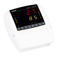
2 GENERAL DESCRIPTION
The XW562K series is fitted with a Real Time Clock which allows programming of up
to eight daily defrost cycles, divided into holidays and workdays.
Model XW562K, 127x123 mm format, is microprocessor based controller suitable for
applications on medium or low temperature refrigerating units. It is provided with six
relay outputs to control 2 compressors, defrost - which can be either electrical or hot
gas - the evaporator fans, the condenser fan and the alarm output. They are also
provided with 3 NTC probe inputs, one for temperature control, the other 2 to control
the defrost end temperature of the evaporators. There are 3 digital inputs (free
contact) for the door switch, the pressure switch and for safety end of defrost.
The electronic controller can work with two parameter lists, switch over by a key.
The standard TTL output allows the user to connect, by means of a TTL/RS485
external module, a ModBUS-RTU compatible monitoring system and to programme
the parameter list with the “Hot Key”.
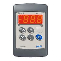
The controller also provides an output for remote keyboard V650 or CX650.
3 CONTROLLING LOADS
3.1 THE COMPRESSORS
The regulation is performed according to the temperature measured by the thermostat
probe with a positive differential from the set point: if the temperature increases and
reaches set point plus differential the compressor is started. The compressor is turned
off when the temperature reaches the set point value again.
In case of fault in the thermostat probe the start and stop of the compressor are timed
through parameters “COn” and “COF”.
3.2 2
ND
COMPRESSOR MANAGEMENT
The relay of the second compressor is activated in parallel with the relay of the first
compressor, with a possible delay set in the AC1 or AC2 parameters, depending on
program 1 or 2. Both the compressors are switched off at the same time.
3.3 DEFROST
2 defrost modes are available through the “tdF” parameter: defrost with electrical
heater or hot gas. The defrost interval is control by means the real time clock,
depending on the hours set in the parameters Ld1..Ld8 on workdays and in
Sd1…Sd8 in holidays for program 1, 2L1.. 2L8 on workdays and in 2S1…2S8 in
holidays for program 2.
At the end of defrost the drip time is controlled through the “Fdt” parameter.
3.4 CONTROL OF EVAPORATOR FANS
The fan control mode is selected by means of the “FnC” parameter for program 1 and
Fn2” parameter for program 2:
C-n fans will switch ON and OFF with the compressor and not run during defrost;
C-y fans will switch ON and OFF with the compressor, also during defrost
After defrost, there is a timed fan delay allowing for drip time, set by means of the
“Fnd” parameter.
O-n fans will run continuously and not run during defrost;
O-y fans will run continuously also during defrost
An additional parameter “FSt” provides the setting of temperature, detected by the
evaporator probe, above which the fans are always OFF. This can be used to make
sure circulation of air only if his temperature is lower than set in “FSt”.
3.5 CONTROL OF CONDENSER FAN
The condenser fan relay is always activated except during defrost. During the defrost
the status of condenser fan depends on the cFE parameter:
with cFE= no the condenser fan doesn’t run during defrost
with cFE= yES the condenser fan runs during defrost
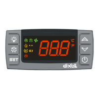
4 KEYBOARD
To display and modify target set point; in programming mode it selects a
parameter or confirms an operation.
By pressing it when the current time is displayed, it allows the User to re-
set the current time and three holidays.
In programming mode it browses the parameter codes or increases the
displayed value.
in programming mode it browses the parameter codes or decreases the
displayed value.
By holding it pressed for 3s the current time is displayed and it permits
the User to enter, Defrost and Clock parameter menu.