Do you have a question about the dixell iPro SERIES and is the answer not in the manual?
Information on proper disposal of electrical and electronic waste according to EU directive.
Details the software environment used for iPRO applications, including ISAGRAF and VISOPROG.
Describes the internal structure of the iPRO programmable controller, including processor and ports.
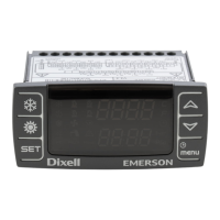
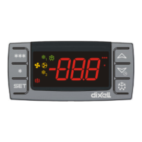
Details the IPG100D and IPC100D series of iPRO controllers.
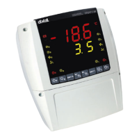
Details the IPG200D series of iPRO controllers, including specific connections and specs.
Details the 4 DIN series of iPRO controllers, covering connections and specifications.
Details the IPX125D and IPX115D models, including their connections and technical specifications.
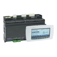
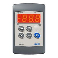
Details the programmable remote LCD display (VISOGRAPH) and its specifications.
Explains the function of LEDs and jumpers on programmable controller devices.
Provides general recommendations for safe and proper installation of iPRO devices.
Details the power supply voltage requirements for iPRO controllers and expansions.
Explains how to connect various types of analogue sensors to the iPRO controllers.
Details the connections for potential-free and live digital inputs on iPRO devices.
Explains how to connect analogue outputs for various applications on iPRO controllers.
Illustrates how to establish a CANBus connection for iPRO devices.
Shows how to connect iPRO devices as RS485 slave devices.
| Brand | dixell |
|---|---|
| Model | iPro SERIES |
| Category | Temperature Controller |
| Language | English |
