1592025700 IPROFAMILY stp GB 2012.08.08.doc iPro Series 28/72
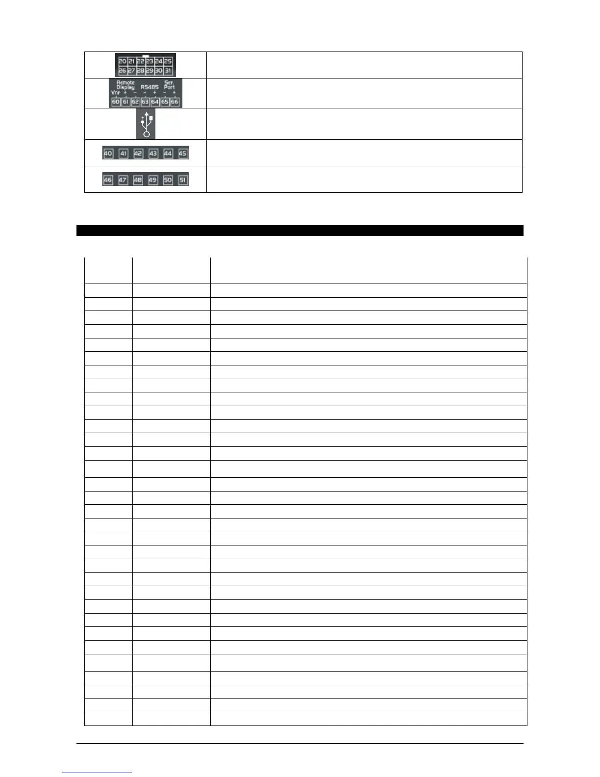
24Vac/dc digital inputs (DI1 - DI11, GND)
Connector for remote terminal (VISOGRAPH), maximum 1 terminal per iPRO.
RS485 Slave connector
Serial port connector (LAN or RS485)
USB port for downloads (BIOS, ISaGRAF® application, maps of parameters, remote display
applications, network configuration, website) and uploads (log files)
Connection with the computer via a USB-ETH converter
Digital relay outputs
4 NO relays, 2 common
Digital relay outputs
4 NO relays, 2 common
4.3.2 Description of the inputs and outputs
Input
No.
Type of Input Description
1 Supply Reference “-“/GND power (24Vac or 24Vdc)
2 Pb1 Configurable analogue input 1 (NTC, PTC, 0 - 20mA, 4 - 20mA, 0 - 10V, 0 - 1V, 0 - 5V, DI)
3 Pb2 Configurable analogue input 2 (NTC, PTC, 0 - 20mA, 4 - 20mA, 0 - 10V, 0 - 1V, 0 - 5V, DI)
4 Pb3 Configurable analogue input 3 (NTC, PTC, 0 - 20mA, 4 - 20mA, 0 - 10V, 0 - 1V, 0 - 5V, DI)
5 +12V Additional power +12Vdc
6 +5V Additional power +5Vdc
7 Out1 Analogue output 1 0 - 10V, 4 - 20mA, Relay
8 Out2 Analogue output 2 0 - 10V, 4 - 20mA, Relay
9 Supply Reference “+“ power supply (24Vac or 24Vdc)
10 Pb4 Configurable analogue input 4 (NTC, PTC, 0 - 20mA, 4 - 20mA, 0 - 10V, 0 - 1V, 0 - 5V, DI)
11 Pb5 Configurable analogue input 5 (NTC, PTC, 0 - 20mA, 4 - 20mA, 0 - 10V, 0 - 1V, 0 - 5V, DI)
12 Pb6 Configurable analogue input 6 (NTC, PTC, 0 - 20mA, 4 - 20mA, 0 - 10V, 0 - 1V, 0 - 5V, DI)
13 PbC Common analogue inputs (NTC, PTC, DI)
14 GND(-)
Additional power reference 5Vdc and 12Vdc, analogue inputs (0 - 20mA, 4 - 20mA, 0 - 10V, 0
- 1V, 0 - 5V), analogue outputs
15 Out3 Analogue output 3 0 - 10V, 4 - 20mA, Relay
16 Out4 Analogue output 4 0 - 10V, 4 - 20mA, Relay
20 DI1 Digital input 1 24Vac/dc
21 DI2 Digital input 2 24Vac/dc
22 DI3 Digital input 3 24Vac/dc
23 DI4 Digital input 4 24Vac/dc
24 DI5 Digital input 5 24Vac/dc
25 DI6 Digital input 6 24Vac/dc
26 DI7 Digital input 7 24Vac/dc
27 DI8 Digital input 8 24Vac/dc
28 DI9 Digital input 9 24Vac/dc
29 DI10 Digital input 10 24Vac/dc
30 DI11 Digital input 11 24Vac/dc
31 GND(-)
Reference “-“ for digital inputs from1 to 11 (if version with dry contacts, this input has
to be used only as common for the digital inputs)
40 C Common relays 1, 2, 3 and 4 (MAX 10A)
41 C Common relays 1, 2, 3 and 4 (MAX 10A)
42 RL1 Relay 1 normally open contact
43 RL2 Relay 2 normally open contact