Do you have a question about the dixell IC200CX Series and is the answer not in the manual?
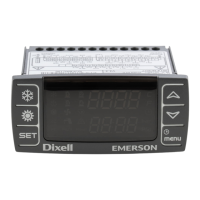
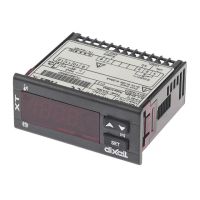
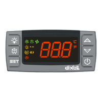
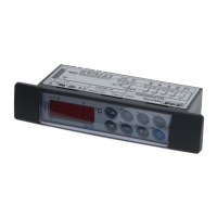
Explains how the device display is configured and presented to the user.
Provides a detailed explanation of the various icons displayed on the controller.
Describes the function and meaning of the LEDs on the bottom display.
Guides users on how to interpret measurement lists shown on the display.
Details how to view probe values for different circuits on the device.
Instructions on how to display the current set point value of the controller.
Steps for adjusting or changing the set point value on the controller.
How to view the active setpoint when energy saving or dynamic setpoint modes are enabled.
Explains the function of each key on the controller's interface.
Details the functions performed by combining multiple key presses.
Information regarding the optional on-board clock feature and its setup.
Step-by-step guide for setting up the Real-Time Clock (RTC).
Details the configuration options for analog inputs PB1, PB2, PB5, and PB6.
Details the configuration options for analog inputs PB3 and PB4.
Explains the configuration for digital inputs ID1 through ID18.
Details the configuration options for digital outputs (relays) RL1 to RL8.
Configuration settings for analog outputs OUT1 and OUT2 (0-10V).
Configuration for analog outputs OUT3 and OUT4 (0-10V / Phase Cut).
Steps to program the instrument using a pre-programmed Hot Key.
Steps to save instrument parameters onto a Hot Key.
Lists the default password values for different programming levels.
Instructions on how to access the Pr1, Pr2, and Pr3 programming levels.
Guide on modifying parameter values within the programming levels.
Procedure for changing the password for each programming level.
Detailed steps to enter the Pr1 (User Level) programming mode.
Detailed steps to enter the Pr2 (Maintenance Level) programming mode.
Detailed steps to enter the Pr3 (OEM Level) programming mode.
How to view and reset the list of active alarms on the controller.
Procedure for resetting compressor overload alarms.
Information on the password required for compressor overload reset.
How to view the historical log of alarm events.
Steps to clear the stored alarm log history.
Details the password setting related to the alarm list.
Instructions for disabling or enabling specific circuits on the unit.
Table detailing the status of loads for "A" type alarms.
Table detailing the status of loads for "B" type alarms.
Table detailing the status of loads for "C" type alarms.
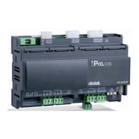
Overview of the hardware inputs, outputs, and connections for the IC206CX model.
Overview of the hardware inputs, outputs, and connections for the 208CX models.
Specifications and instructions for the panel cut-out dimensions for mounting.
Cut-out dimensions for mounting vertical boards VI620CX.
| Series | IC200CX |
|---|---|
| Category | Temperature Controller |
| Input Type | Thermocouple, RTD, Analog |
| Display | LCD |
| Probe Inputs | 1 |
| Output Type | Relay |
| Power Supply | 24V AC/DC |
| Operating Temperature | 0 to 60 °C (32 to 140 °F) |
| Storage Temperature | -20°C to 70°C |
| Resolution | 0.1 °C |
| Digital Inputs | Configurable |
| Relay Outputs | Up to 2 (depending on model) |
| Control Algorithm | On/Off, PID |
| Dimensions | 48 x 48 x 100 mm |
| Protection Rating | IP20 |