Do you have a question about the dixell XT110C and is the answer not in the manual?
Manual is part of the product; keep it for reference. Do not use as safety device.
Check supply voltage, avoid water/moisture, disconnect before maintenance, do not open.
Pre-set probe type is on the label. Set probe following the procedure if different.
Enter programming menu, select Pbc parameter, set probe type, confirm, switch off/on.
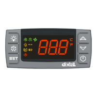
SET to lock/unlock keyboard. SET+▾ to enter programming. SET+▲ to return to display.
Press SET key for >4s to switch OFF if function enabled (onF=yES). Press SET to switch ON.
Browses parameters or increases displayed value. Hold for faster change.
Browses parameters or decreases displayed value. Hold for faster change.
Intervention differential for set point. Can be set with positive or negative value.
Sets the minimum acceptable value for the set point.
Sets the maximum acceptable value for set point.
Defines action type: inverse (heating) or direct (cooling).
Minimum time between switching off and following switching on.
Minimum time a stage stays switched ON.
Determines if alarms are relative to set point or absolute values.
Sets the minimum alarm threshold, relative or absolute.
Sets the maximum alarm threshold, relative or absolute.
Alarm recovery differential; value above alarm threshold for recovery.
Time interval between alarm detection and signalling.
Delay for alarm signalling after instrument power on.
Defines relay status (open/closed) when probe is faulty.
Determines if alarm relay is disabled by pressing a key (XT111C/D only).
Configures alarm relay state (open/closed) with alarm (XT111C/D only).
Adjusts read-out for 4mA or 0V input signal.
Adjusts read-out for 20mA, 1V or 10V input signal.
Allows adjustment of possible offset of the probe.
Selects the resolution of the controller (integer or decimal points).
Sets the measurement unit (°C, °F, %RH, bar, PSI, etc.).
Sets the kind of probe to be used by the controller.
Selects 2 or 3 wires for Pt100 probes.
Determines analog output relation to probe reading or set point.
Minimum value associated with 4mA analog output.
Maximum value associated with 20mA analog output.
Defines analog output state on probe fault.
Sets set point variation during Energy Saving cycle.
Configures digital input function (e.g., Energy Saving, Alarm).
Defines if digital input is activated by closing or opening the contact.
Delay between detection of external alarm and its signalling.
Identifies the instrument within a control or supervising system.
Permits switching ON/OFF of the instrument by pressing SET key for >4s.
Read only: Shows the code of the parameters map.
Read only: Shows the software release version.
Access to the Pr2 parameter programming menu.
Programs a Hot Key by uploading settings from the instrument.
Downloads settings from a programmed Hot Key to the instrument.
Inverts the regulation of the controller: from direct to inverse and viceversa.
Allows switching ON and OFF the instrument via digital input.
Activates a generic alarm signal after a delay when digital input is triggered.
Activates a serious alarm and switches off outputs when digital input is triggered.
Changes set point value during Energy Saving cycle, enabled until input is activated.
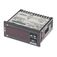
Connection diagram for XT110C with 12V/24V AC/DC supply.
Connection diagram for XT110C with 230V/115V AC supply.
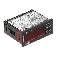
Connection diagram for XT111C with 12V/24V AC/DC supply.
Connection diagram for XT111C with 230V/115V AC supply.
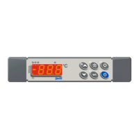
Connection diagram for XT110D with 230V/120V/24V AC supply.
Sets the target temperature value for regulation.
Intervention differential for set point.
Sets the minimum acceptable value for the set point.
Sets the maximum acceptable value for set point.
Defines action type: inverse (heating) or direct (cooling).
Minimum time between switching off and following switching on.
Minimum time a stage stays switched ON.
Determines if alarms are relative to set point or absolute values.
Sets the minimum alarm threshold, relative or absolute.
Sets the maximum alarm threshold, relative or absolute.
Alarm recovery differential; value above alarm threshold for recovery.
Time interval between alarm detection and signalling.
Delay for alarm signalling after instrument power on.
Defines relay status (open/closed) when probe is faulty.
Determines if alarm relay is disabled by pressing a key (XT111C/D only).
Configures alarm relay state (open/closed) with alarm (XT111C/D only).
Adjusts read-out for 4mA or 0V input signal.
Adjusts read-out for 20mA, 1V or 10V input signal.
Allows adjustment of possible offset of the probe.
Selects the resolution of the controller (integer or decimal points).
Sets the measurement unit (°C, °F, %RH, bar, PSI, etc.).
Sets the kind of probe to be used by the controller.
Selects 2 or 3 wires for Pt100 probes.
Determines analog output relation to probe reading or set point.
Minimum value associated with 4mA analog output.
Maximum value associated with 20mA analog output.
Defines analog output state on probe fault.
Sets set point variation during Energy Saving cycle.
Configures digital input function (e.g., Energy Saving, Alarm).
Defines if digital input is activated by closing or opening the contact.
Delay between detection of external alarm and its signalling.
Identifies the instrument within a control or supervising system.
Permits switching ON/OFF of the instrument by pressing SET key for >4s.
Read only: Shows the code of the parameters map.
Read only: Shows the software release version.
Access to the Pr2 parameter programming menu.
| Brand | dixell |
|---|---|
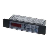
| Model | XT110C |
| Category | Temperature Controller |
| Language | English |