dIXEL
Installing and Operating Instructions
1592002211
FOR UPDATING 1592002211 XT110-111C-D GB R.1.0 15.12.2004 XT110C – XT111C - XT110D – XT111D 3/4
“PFc” Probe short circuited Alarm output ON; Output according to parameter “So1”
“HA” Maximum alarm Alarm output ON; Other outputs unchanged.
“LA” Minimum alarm Alarm output ON; Other outputs unchanged.
“EAL” External alarm Output unchanged.
“bAL” Serious external alarm Output OFF.
12.1 ALARM RELAY STATUS
Status of the instrument XT111C XT111D
AS = CL AS= oP AS = CL AS= oP
Instrument off 4-6 closed 4-6 closed 20-21 closed 20-21 closed
Normal operating 4-6 closed 4-6 open 20-21 closed 20-21 open
Alarm present 4-6 open 4-6 closed 20-21 open 20-21 closed
12.2 SILENCING BUZZER / ALARM RELAY OUTPUT
Once the alarm signal is detected the buzzer, if present, can be disabled by pressing any key.
XT111C/XT111D: the alarm relay status depends on the tbA parameter: with tbA=yES the relay is
disabled by pressing any key, with tbA=no the alarm relay remains enabled as long as the alarm lasts.
The display signal remains as long as the alarm condition remains.
12.3 ALARM RECOVERY
Probe alarms “PFo”, “PFc” start few seconds after the fault in the probe; they automatically stop few
seconds after the probe restarts normal operation. Check connections before replacing the probe.
Max. and min. alarms “HA” and “LA” automatically stop as soon as the variable returns to normal values.
Alarms “bAL” and “EAL” recover as soon as the digital input is disabled.
13. TECHNICAL DATA
Housing: self extinguishing ABS.
Case: XT110C, XT111C:frontal 32x74 mm; depth 60mm;
XT110D, XT111D: 4 DIN modules 70x85 mm; depth 61mm.
Mounting: XT110C, XT111C panel mounting in a 71x29 mm panel cut-out.
XT110D, XT111D: DIN RAIL
Protection: IP20.
Frontal protection: XT110C, XT111C IP65 with frontal gasket RG-C (optional).
Connections: Screw terminal block ≤ 2,5 mm
2
heat-resistant wiring.
Power supply: 12Vac/dc, ±10% or: 24Vac/dc ± 10% only for “C” format
or 230Vac ± 10%, 50/60Hz or 110Vac, ± 10%, 50/60Hz
Power absorption: 3VA max.
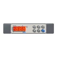
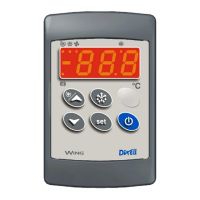
Display: 3 ½ digits, red LED
Inputs: according to the order: NTC/PTC or NTC/PTC /Pt100 /Thermocouple J, K, S or 4÷20mA/ 0÷1V /
0÷10V
Relay outputs: Load relay SPDT 8(3)A, 250Vac
Alarm: (XT111C/XT111D) relay SPDT 8(3)A, 250Vac
Other output: buzzer (optional)
Kind of action: 1B; Pollution grade: normal, Software class: A;
Data storing: on the non-volatile memory (EEPROM);
Operating temperature: 0÷60 °C (32÷140°F); Storage temperature: -30÷85 °C (-22÷185°F).
Relative humidity: 20÷85% (no condensing)
Measuring and regulation range: according to the probe;
Controller Accuracy a 25°C: better than ±0,5% of full scale
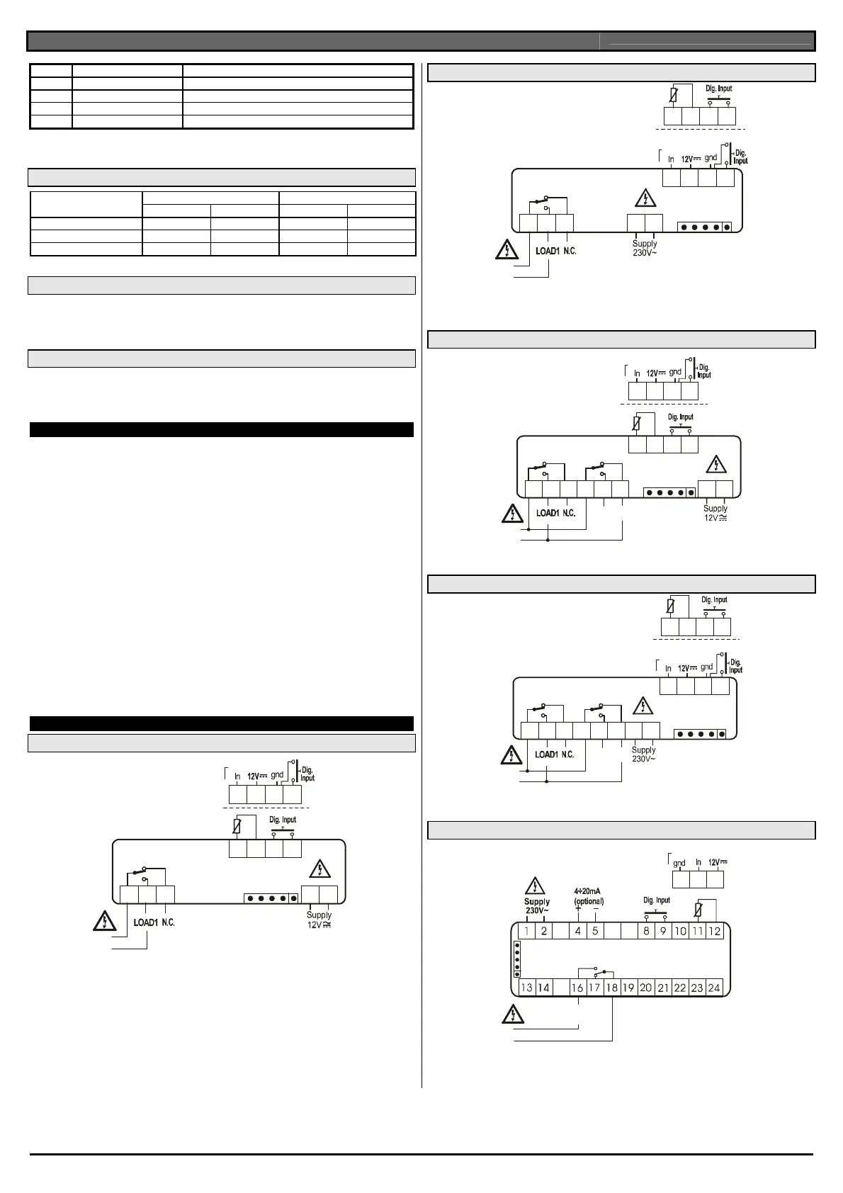
14. CONNECTIONS
14.1 XT110C – 12V AC/DC OR 24V AC/DC
123456 11 12
789
10
Hot-KEY
8(3)A250V
Line
Input: 4÷20mA
0÷1V / 0÷10V
78910
PTC / NTC
Probe: Pt100= 7 – 9 (8); Thermocouple J, K, S = 7(+); 9(-)
24Vac/cd supply: 11-12
14.2 XT110C – 230V AC OR 115V AC
123456 78
9101112
Hot-KEY
8(3)A250V
Line
Input 4÷20mA
0÷1V / 0÷10V
9101112
PTC / NTC
Pt100=9 –11 (10); Thermocouple J, K, S = 9(+) - 11(-)
115Vac supply: 7-8
14.3 XT111C – 12VAC/DC OR 24VAC/DC
1
2
3
4
5 6 11 12
78910
Hot-KEY
8(3)A250V 8(3)A250V
Line
ALARM
N.O.
Input: 4÷20mA
0÷1V / 0÷10V
78910
PTC / NTC
Probe: Pt100= 7 – 9 (8); Thermocouple J, K, S = 7(+); 9(-)
24Vac/cd supply: 11-12
14.4 XT111C – 230V AC OR 115V AC
12
3
4
5
678
9101112
Hot-KEY
8(3)A250V 8(3)A250V
Line
Alarm
N.O.
Input 4÷20mA
0÷1V / 0÷10V
91011
12
PTC / NTC
Probe: Pt100=9–11 (10); Thermocouple J, K, S= 9(+) - 11(-)
115Vac supply: 7-8
14.5 XT110D – 230V AC OR 120V AC OR 24V AC
Input: 4÷20mA
0÷1V / 0÷10V
10 11 12
PTC
NTC
Analog
Out
8(3)A250V
Line
LOAD 1
Hot-KEY
Probe: Pt100=11 - 10 (12); Thermocouple J, K, S= 11(+) - 10(-)
115Vac supply: 1-2; 24Vac supply: 1-2

 Loading...