1592018110 XR460C GB r1.0 04.07.2005 XR460C 1/5
XR460C
DUAL TEMPERATURE CONTROLLER
Contents
1. GENERAL WARNING __________________________________________________________ 1
2. GENERAL DESCRIPTION_______________________________________________________ 1
3. TEMPERATURE CONTROL _____________________________________________________ 1
4. DEFROST ___________________________________________________________________ 1
5. CONTROL OF EVAPORATOR FANS (ONLY FOR SECTION 1)_________________________ 1
6. THE DISPLAY ________________________________________________________________ 1
7. PARAMETER LIST_____________________________________________________________ 2
8. DIGITAL INPUT _______________________________________________________________ 4
9. INSTALLATION AND MOUNTING_________________________________________________ 4
10. ELECTRICAL CONNECTIONS ___________________________________________________ 4
11. SERIAL LINE _________________________________________________________________ 4
12. USE OF THE PROGRAMMING “HOT KEY “ ________________________________________ 4
13. ALARM SIGNALS______________________________________________________________ 4
14. TECHNICAL DATA_____________________________________________________________ 5
15. WIRING CONNECTIONS _______________________________________________________ 5
16. DEFAULT SETTING VALUES____________________________________________________ 5
1. GENERAL WARNING
1.1 PLEASE READ BEFORE USING THIS MANUAL
This manual is part of the product and should be kept near the instrument for easy and quick
reference.
The instrument shall not be used for purposes different from those described hereunder. It cannot be
used as a safety device.
Check the application limits before proceeding.
1.2 SAFETY PRECAUTIONS
Check the supply voltage is correct before connecting the instrument.
Do not expose to water or moisture: use the controller only within the operating limits avoiding
sudden temperature changes with high atmospheric humidity to prevent formation of
condensation
Warning: disconnect all electrical connections before any kind of maintenance.
Fit the probe where it is not accessible by the End User. The instrument must not be opened.
In case of failure or faulty operation send the instrument back to the distributor or to “Dixell S.p.A.”
(see address) with a detailed description of the fault.
Consider the maximum current which can be applied to each relay (see Technical Data).
Ensure that the wires for probes, loads and the power supply are separated and far enough from
each other, without crossing or intertwining.
In case of applications in industrial environments, the use of mains filters (our mod. FT1) in parallel
with inductive loads could be useful.
2. GENERAL DESCRIPTION
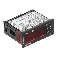
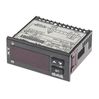
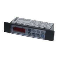
Model XR460C, 32x74 mm format, is a microprocessor based controller, able to control 2
temperatures in an independent way.
The first section is suitable for applications on medium or low temperature refrigerating units. It is
provided with 3 relay outputs to control compressor, defrost - which can be either electrical or hot
gas - and the evaporator fans. It is also provided with 2 NTC or PTC probe inputs, one for
temperature control the other one to control the defrost end temperature of the evaporator.
The second section is suitable for applications on medium or normal temperature refrigerating
units, with timed defrost. It’s provided with 1 relay output to control compressor. It is also provided
with 1 NTC/PTC probe inputs, for temperature control.
There are two digital inputs (free contact) completely configurable by parameter.
The standard TTL output allows the user to connect, by means of a TTL/RS485 external module, a
ModBUS-RTU compatible monitoring system and to programme the parameter list with the “Hot
Key”.
3. TEMPERATURE CONTROL
3.1 THE COMPRESSOR 1 (2)
For each section, the regulation is
performed according to the
temperature measured by its own
thermostat probe with a positive
differential from the set point.
If the temperature increases and
reaches set point1 (2) plus
differential1 (2) the compressor is
started and then turned off when the
temperature reaches the set point
value again.
In case of fault in the thermostat probe the start and stop of the compressor are timed through
parameters “COn1(2)” and “COF1(2)”.
4. DEFROST
4.1 SECTION 1
For the section 1 two defrost modes are available through the “tdF1” parameter:
tdF1= rE defrost with electrical heater
tdF1= in or hot gas.
The defrost interval is control by means of parameter “EdF”:
rtc (only for instruments with RTC): beginning of defrost cycles is set by the L1d1÷L1d6
parameters during the working days and S1d1÷S1d6 during the holidays
in the defrost is made every “IdF” time
Sd the interval “IdF” is calculate through Smart Defrost algorithm (only when the compressor is ON)
At the end of defrost the drip time is controlled through the “Fdt” parameter.
4.2 SECTION 2
For the section 2 the defrost interval is control by means of parameter “EdF2”: with EdF=in the
defrost is made every “IdF2” time, with EdF2=Sd the interval “IdF2” is calculate through Smart
Defrost algorithm (only when the compressor 2 is ON).
Defrost is performed through a simple stop of the compressor2. Parameter “IdF2” controls the
interval between defrost cycles, while its length is controlled by parameter “MdF2”.
4.3 RELATION BETWEEN DEFROSTS
Different kinds of defrosts are available for each section.
The relation between defrosts is set by the dFS parameter: relation between defrosts.
4 relation between the 2 sections of the controller are available, to manage different kinds of
applications:
in = independent defrosts;
StS = same defrost start, synchronised defrost end;
St = same defrost start, independent defrost end;
SE = sequential defrost;
4.3.1 dFS= in - independent defrosts
The defrosts of the 2 sections of controller are completely independent.
First section: defrost interval is set by idF1 parameter.
Second section: defrost interval is set by idF2 parameter.
The defrost interval is control by means of parameter “EdF1(2)”:
in the defrost is made every “IdF” time
Sd the interval “IdF” is calculate through Smart Defrost algorithm (only when the compressor is ON)
Manual defrost activation, by pushing the DOWN key (defrost 1) or UP key (defrost 2).
By pushing the Down key or Up key for 3s, a defrost request is generated for section 1 or 2
respectively. The defrost interval is re-loaded.
4.3.2 dFS = StS – Same defrost start, end defrost synchronised or dFS = St
- Same defrost start, end defrost independent.
The defrost of the 2 sections of controller starts at the same time. idF1 parameter sets the defrost
interval for both the sections. The defrosts are performed at regular interval if EdF1 = in or according
to the Smartdefrost algorithm if EdF1 = Sd.
With dFS = StS regulation restarts only when defrost is finished for both the sections. The section
that finishes the defrost before the other starts dripping time until also the other section has not
finished its defrost.
Manual defrost activation, by pushing the DOWN key (defrost 1) or UP key (defrost 2).
By pushing the Down key or Up key for 3s, a defrost request is generated for both the sections 1 and
2. The defrost interval is re-loaded.
With dFS = St each section restarts regulation as soon as its defrost is finished.
4.3.3 dFS = SE – sequential defrost
The defrost of 2 sections is synchronised. idF1 parameter sets the defrost interval for both the
sections. Defrosts are performed at regular interval if EdF1 = in or according to the Smartdefrost
algorithm if EdF1 = Sd. Section 1 does its defrost first, at the end of the defrost of section 1, section
2 starts its defrost..
Manual defrost activation, by pushing the DOWN key (defrost 1) or UP key (defrost 2).
By pushing the Down key or Up key for 3s, a defrost request is generated for both the sections 1 and
2. The defrost interval is re-loaded.
5. CONTROL OF EVAPORATOR FANS (ONLY FOR SECTION 1)
Section 1 has 1 relay to control evaporator fan.
The fan control mode is selected by means of the “FnC1” parameter:
FnC1=C-n fans will switch ON and OFF with the compressor and not run during defrost:;
FnC1= O-n fans will run continuously, but not during defrost
After defrost, there is a timed fan delay allowing for drip time, set by means of the “Fnd1” parameter.
FnC1=C-y fans will switch ON and OFF with the compressor and run during defrost;
FnC1=O-y fans will run continuously also during defrost
An additional parameter “FSt1” provides the setting of temperature, detected by the evaporator
probe, above which the fans are always OFF. This can be used to make sure circulation of air only if
his temperature is lower than set in “FSt1”.