dIXEL
Installing and Operating Instructions
1592018110
1592018110 XR460C GB r1.0 04.07.2005 XR460C 5/5
Frontal protection: IP65 with frontal gasket RG-C (optional).
Connections: Screw terminal block ≤ 2,5 mm
2
heat-resistant wiring.
Power supply: 12Vac/dc (opt.24Vac/dc), ±10%
Power absorption: 5VA max.
Inputs: 3 NTC or PTC probes
Relay outputs
compressor1: SPST relay 8(3) A, 250Vac or
compressor 2: relay SPDT 8(3) A, 250Vac
defrost: relay SPDT 8(3) A, 250Vac
fans: relay SPST 8(3) A, 250Vac
Other output: Alarm buzzer
Kind of action: 1B.; Pollution grade: normal; Software class: A.
Data storing: on the non-volatile memory (EEPROM).
Operating temperature: 0÷60 °C.
Storage temperature: -25÷60 °C.
Relative humidity: 20÷85% (no condensing)
Measuring and regulation range: -40÷110°C (-58÷230°F)
Resolution: 0,1 °C or 1°C or 1 °F (selectable).
Accuracy (ambient temp. 25°C): range -40÷50°C (-40÷122°F): ±0,5 °C ±1 digit
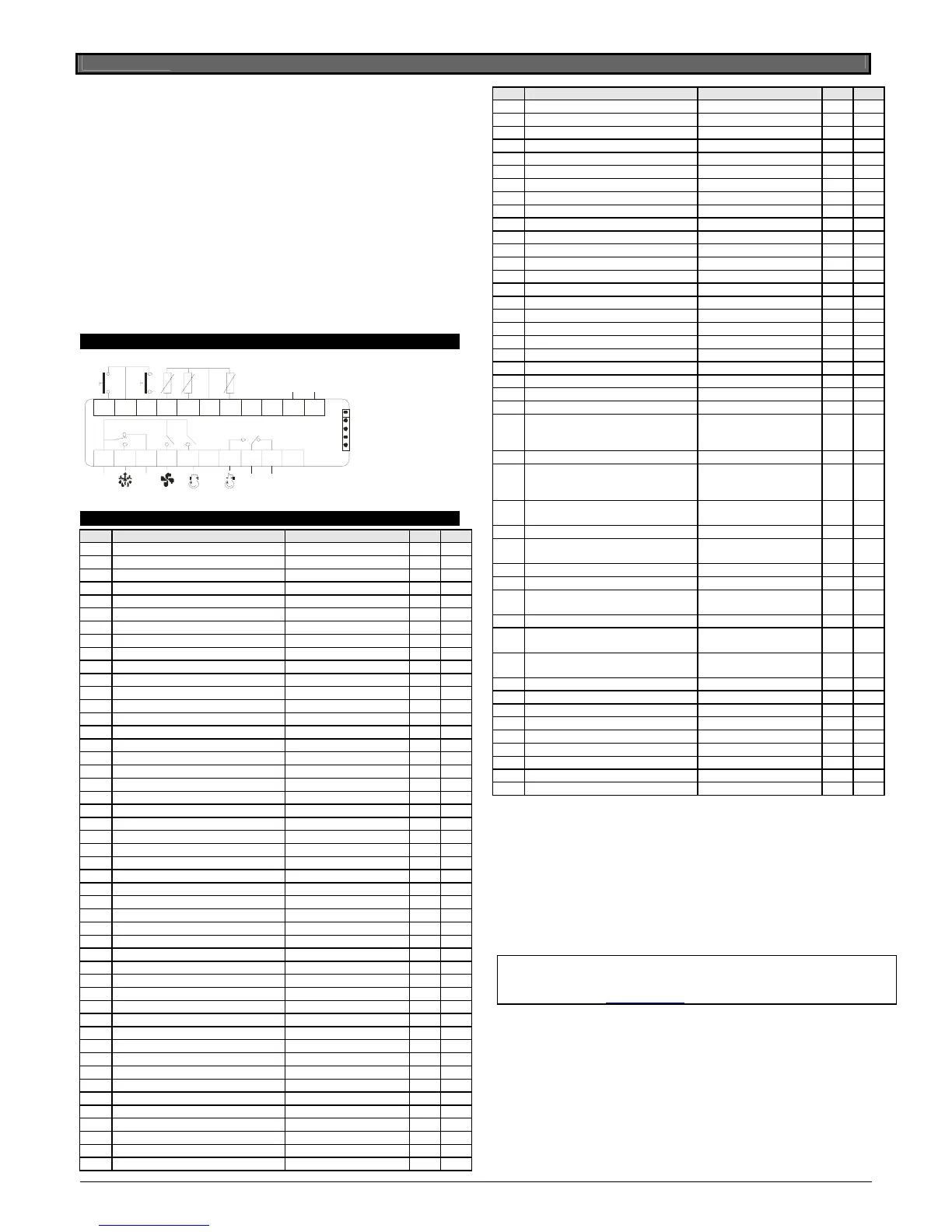
15. WIRING CONNECTIONS
N.C.Line
8(3)A250 V~
8(3)A
8(3)A
Ma x
16A
Comp1
Def Fan
Room1
1
2
3
4
5
Config.2
Config.1
N.C.
8(3)A
7
89
Line
Comp2
Ho t K e y
13 14 15 16 17 18 19 20 21
22
23
Supply
12V=
Def.
Room2
16. DEFAULT SETTING VALUES
Label Nome Range Default
Set1 Set point 1 LS1÷US1 -5 Pr1
Set2 Set point 2 LS2÷US2 3 Pr1
Hy1 Differential 1 0,1÷25,5 °C / 1÷45°F 2.0 Pr1
Hy2 Differential 2 0,1÷25,5 °C / 1÷45°F 2.0 Pr1
REGULATION – SECTION 1
LS1 Minimum set point1 limit -50,0°C÷SET1 / -58°F÷SET1 -50.0 Pr2
US1 Maximum set point1 limit SET1 ÷ 150°C / SET1 ÷ 302°F
110 Pr2
odS1 Outputs activation delay of sect. 1 at start up 0÷255 min. 0 Pr2
Ac1 Anti-short cycle delay for compressor1 0÷30 min. 1 Pr1
con1 Compressor1 ON time with faulty probe1 0÷255 min. 15 Pr2
coF1 Compressor1 OFF time with faulty probe1 0÷255 min. 15 Pr2
cH1 Kind of action for section 1 cL / Ht cL Pr2
REGULATION – SECTION 2
LS2 Minimum set point2 limit -50,0°C÷SET2 / -58°F÷SET2 -50.0 Pr2
US2 Maximum set point2 limit SET2 ÷ 150°C / SET2 ÷ 302°F
110 Pr2
odS2 Outputs activation delay of sect. 2 at start up 0÷255 min. 0 Pr2
Ac2 Anti-short cycle delay for compressor2 0÷30 min. 1 Pr1
con2 Compressor2 ON time with faulty probe2 0÷255 min. 15 Pr2
coF2 Compressor2 OFF time with faulty probe2 0÷255 min. 15 Pr2
cH2 Kind of action for section 2 cL / Ht cL Pr2
DISPLAY
cF Temperature measurement unit °C / °F °C Pr2
rES Resolution (for °C in ÷ de dE Pr1
Lod1 Bottom display visualization P1 ÷ P4 P1 Pr2
Lod2 Upper display visualization P1 ÷ P4 P2 Pr2
DEFROST
dFS Relation between defrosts ind; StS; Sti, SE ind Pr2
tdF1 Kind of defrost section 1 rE, in rE Pr2
EdF1 Defrost mode, section 1 In, Sd,RTC in Pr2
SdF1 Set point for Smart Defrost section 1 -30 ÷ +30°C / -22÷+86°F 0 Pr2
dtE1 End defrost temperature section 1 -50,0÷110°C/ -58÷230°F 6.0 Pr2
idF1 Interval between defrosts, section 1 1÷120ore 6 Pr1
MdF1 Maximum duration of defrost, section 1 0÷255 min. 20 Pr1
tPF1 Pre-defrost compressor on time 0÷30 min. 0 Pr2
Fdt1 Dripping time section 1. 1 0÷60 min. 0 Pr2
dPo1 Defrost at power on section . 1 n ÷ y n Pr2
EdF2 Defrost mode, section 2: In, Sd, RTC in Pr2
idF2 Interval between defrosts, section 2 1÷120ore 8 Pr1
MdF2 (Maximum) duration of defrost, section 2 0÷255 min. 20 Pr1
dFd Display during defrost rt, it, SEt, dEF, dEG it Pr2
dAd Defrost display time out 0÷255 min. 20 Pr2
dSd Defrost delay 0÷255 min. 0 Pr2
FANS
FnC1 Fans operating mode, section 1 C-n, C-y, O-n, O-y O-n Pr2
Fnd1 Fans delay after defrost, section 1 0÷255 min. 10 Pr2
FSt1 Fans stop temperature, section 1 -50,0÷110°C/ -58÷230°F 2.0 Pr2
FAP1 Probe for fans P1÷P3 P3 Pr2
Label Nome Range Default
ALc1 Temperature alarms configuration, section 1 rE / Ab Ab Pr2
ALu1 Maximum alarm, section 1 -50,0÷150°C/ -58÷302°F 110 Pr1
ALL1 Minimum alarm, section 1 -50,0÷150°C/ -58÷302°F -50.0 Pr1
ALd1 Temperature alarm delay, section 1 0÷255 min. 15 Pr2
dAo1 Delay of temp. alarm at start-up, section 1 0 ÷ 23h 50 min. 1.3 Pr2
ALc2 Temp. alarms configuration, section 2 re ÷ Ab Ab Pr2
ALu2 Maximum alarm, section 2 -50,0÷150°C/ -58÷302°F 110 Pr1
ALL2 Minimum alarm, section 2 -50,0÷150°C/ -58÷302°F -50.0 Pr1
ALd2 Temperature alarm delay, section 2 0÷255 min. 15 Pr2
dAo2 Delay of temp. alarm at start-up, section 2 0 ÷ 23h 50 min. 1.3 Pr2
AFH Temperature alarm and fan differential 0,1÷25,5 °C / 1÷45°F 1.0 Pr2
EdA Alarm delay at the end of defrost 0÷255 min. 20 Pr2
dot Delay of temp. alarm after closing the door 0÷255 min. 20 Pr2
doA Open door alarm delay 0÷254 min., nu 15 Pr2
Pbc Kind of probe PTC/ntc ntc Pr2
ANALOGUE INPUTS
oFS1 Thermostat1 probe calibration -12,0÷12,0°C / -21÷21°F 0.0 Pr2
oFS2 Thermostat2 probe calibration -12,0÷12,0°C / -21÷21°F 0.0 Pr2
oFS3 Evaporator probe calibration -12,0÷12,0°C / -21÷21°F 0.0 Pr2
P2P Thermostat2 probe presence n / y Y Pr2
P3P Evaporator probe presence n ÷ y Y Pr2
DIGITAL INPUTS
i1P Digital input 1 polarity cL÷OP cL Pr2
i1F Digital input 1 operating mode
MP1; MP2, MP; EA1; EA2;
EAL; bA1; bA2; , bAL; dF1;
dF2; dEF; oF1; oF2; oFF; ES
MP1 Pr2
i2P Digital input 2 polarity cL÷OP cL Pr2
i2F Digital input 2 operating mode
MP1; MP2, MP; EA1; EA2;
EAL; bA1; bA2; , bAL; dF1;
dF2; dEF; oF1; oF2; oFF; ES
MP2 Pr2
odc1 Comp. and fan status when open door, sect
1
no, Fan, CPr, F_C
FAn Pr2
rrd1 Outputs restart after door open alarm, sect. 1 n, y Y Pr2
did1 Time interval delay for digital input alarm,
sect. 1
0÷255 min.
15 Pr2
odc2 Comp. status when open door, section 2: no, Fan, CPr, F_C no Pr2
rrd2 Outputs restart after door open alarm, sect. 2 n, y Y Pr2
did2 Time interval delay for digital input alarm,
sect. 2
0÷255 min.
5 Pr2
OTHER
HES1 Temp. increase during the Energy Saving
cycle, sect. 1
-30÷30°C / -54÷54°F 0 Pr2
HES2 Temp. increase during the Energy Saving
cycle, section 2
-30÷30°C / -54÷54°F 0 Pr2
Adr1 RS485 serial address, section 1 1÷247 1 Pr2
Adr2 RS485 serial address, section 2 1÷247 1 Pr2
dP1 Thermostat 1 probe value - - - - - - Pr1
dP2 Thermostat 2 probe value - - - - - - Pr1
dP3 Evaporator probe value - - - - - - Pr1
onF Stand-by function y, n - - - Pr2
rEL Release software --- - - - Pr2
Ptb Parameter table - - - - - - Pr2
Pr2 Access to the protected parameter list - - - Pr1
Dixell S.p.A.
Via dell’Industria, 27 - 32010 Z.I Pieve d’Alpago (BL) ITALY
tel. +39 - 0437 - 98 33 - fax +39 - 0437 - 98 93 13 –
E-mail:dixell@dixell.com - http://www.dixell.com
 Loading...