1592026020 XW60K GB R2.1 22.06.2012.doc XW60K 5/6
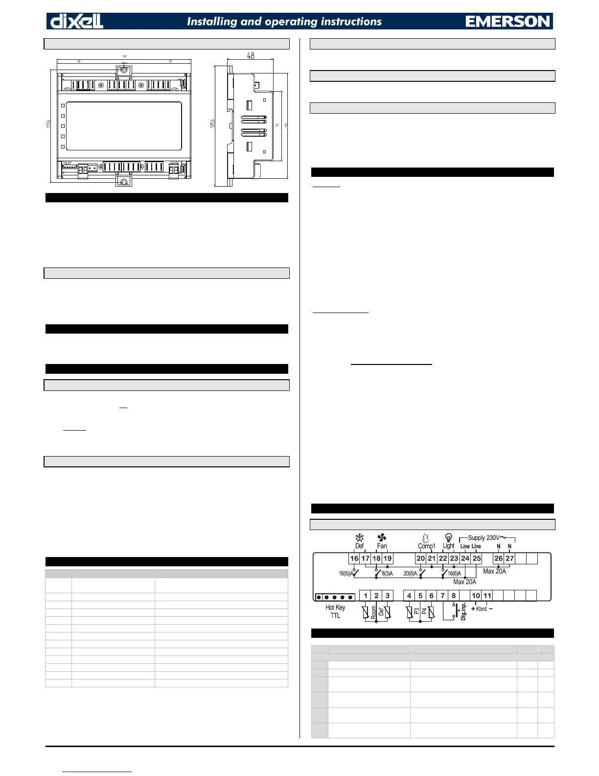
10.1 XW60K – 8 DIN CASE - DIMENSIONS
11 ELECTRICAL CONNECTIONS
XW60K is provided with screw terminal blocks to connect cables with a cross section up to 2.5 mm
2
for
the RS485 (optional) and the keyboard. To connect the other inputs, power supply and relays, XW60K
is provided with Faston connections (6.3mm). Heat-resistant cables have to be used. Before
connecting cables make sure the power supply complies with the instrument’s requirements. Separate
the probe cables from the power supply cables, from the outputs and the power connections. Do not
exceed the maximum current allowed on each relay, in case of heavier loads use a suitable external
relay.
NOTE: the maximum current allowed for all the loads is 20A.
11.1 PROBE CONNECTIONS
The probes shall be mounted with the bulb upwards to prevent damages due to casual liquid
infiltration. It is recommended to place the thermostat probe away from air streams to correctly
measure the average room temperature. Place the defrost termination probe among the evaporator
fins in the coldest place, where most ice is formed, far from heaters or from the warmest place during
defrost, to prevent premature defrost termination.
12 TTL/RS485 SERIAL LINE
The TTL connector allows, by means of the external module TTL/RS485 (XJ485CX), to connect the
unit to a network line ModBUS-RTU compatible as the dIXEL monitoring system. The same TTL
connector is used to upload and download the parameter list of the “HOT-KEY”.
13 HOW TO: USE OF THE PROGRAMMING “HOT KEY”
13.1 PROGRAM A HOT-KEY FROM AN INSTRUMENT (UPLOAD)
1. Program one controller with the front keypad.
2. When the controller is ON, insert the “HOT-KEY” and push UP button; the “uPL” message
appears followed a by a flashing “End” label.
3. Push SET button and the “End” will stop flashing.
4. Turn OFF the instrument, remove the “HOT-KEY” and then turn it ON again.
NOTE: the “Err” message appears in case of a failed programming operation. In this case push again
button if you want to restart the upload again or remove the “HOT-KEY” to abort the operation.
13.2 PROGRAM AN INSTRUMENT BY USING A HOT-KEY (DOWNLOAD)
1. Turn OFF the instrument.
2. Insert a pre-programmed “HOT-KEY” into the 5-PIN receptacle and then turn the Controller
ON.
3. The parameter list of the “HOT-KEY” will be automatically downloaded into the Controller
memory. The “doL” message will blink followed a by a flashing “End” label.
4. After 10 seconds the instrument will restart working with the new parameters.
5. Remove the “HOT-KEY”.
NOTE: the message “Err” is displayed for failed programming. In this case turn the unit off and then on
if you want to restart the download again or remove the “HOT-KEY” to abort the operation.
14 ALARM SIGNALS
Message
parameters Con and CoF.
P2 Evaporator probe failure Alarm output ON; Other outputs unchanged
P3 Probe 3 probe failure Alarm output ON; Other outputs unchanged
P4 Probe 4 probe failure Alarm output ON; Other outputs unchanged
HA Maximum temperature alarm Alarm output ON; Other outputs unchanged
LA Minimum temperature alarm Alarm output ON; Other outputs unchanged
HA2 Condenser high temperature It depends on the AC2 parameter
LA2 Condenser low temperature It depends on the bLL parameter
dA Door open Compressor and fans restarts
EA External alarm Output unchanged.
CA Serious external alarm (i1F=bAL) All outputs OFF.
CA Pressure switch alarm (i1F=PAL) All outputs OFF
EE Data or memory failure Alarm output ON; Other outputs unchanged
The alarm message is displayed until the alarm condition is recovery.
All the alarm messages are showed alternating with the room temperature except for the “P1” which is
flashing.
To reset the “EE” alarm and restart the normal functioning press any key, the “rSt” message is
displayed for about 3 sec.
14.1 SILENCING BUZZER
Once the alarm signal is detected the buzzer can be silenced by pressing any key. Buzzer is mounted
in the keyboard and it is an option.
14.2 “EE” ALARM
The dIXEL instruments are provided with an internal check for the data integrity. The “EE” alarm
flashes when a failure in the memory data occurs. In such cases the alarm output is enabled.
14.3 ALARM RECOVERY
Probe alarms: “P1” (probe1 faulty), “P2”, “P3” and “P4”; they automatically stop 10 sec after the probe
restarts normal operation. Check connections before replacing the probe.
Temperature alarms “HA”, “LA” “HA2” and “LA2” automatically stop as soon as the temperature
returns to normal values.
Alarms “EA” and “CA” (with i1F=bAL) recover as soon as the digital input is disabled.
Alarm “CA” (with i1F=PAL) recovers only by switching off and on the instrument.
15 Technical data
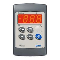
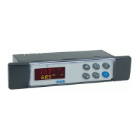
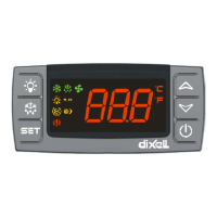
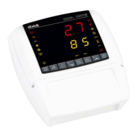
Keyboards
Housing: self extinguishing ABS
Case: T620 and T620T: facia 38x185 mm; depth 23mm
V620: facia 72x56 mm; depth 23mm
CX620: facia 75x36 mm; depth 23mm
Mounting: T620T panel mounting in a 150x31 mm panel cut-out with the 2 metal brackets supplied.
T620: panel mounting in a 150x31 mm panel cut-out with two screws. 3 x 2mm. Distance
between the holes 165mm
V620: panel mounting in a 56x72 mm panel cut-out with two screws. 3x2mm. Distance
between the holes 40mm
CX620: panel mounting in a 71x29mm panel cut-out
Protection: IP20; Frontal protection: IP65 with frontal gasket
Connections: Screw terminal block 2.5 mm
2
Power supply: from XW60K power module
Display: 3 digits, red LED, 14.2 mm high
Optional output: buzzer.
Power module XW60K
Case: 8 DN: 140X176X148
Connections: Screw terminal block 2.5 mm
2
heat-resistant wiring and 6.3mm Faston
Power supply: 230Vac or. 110Vac 10% or 24Vac
Power absorption: 10VA max
Inputs: 4 NTC or PTC probes
Digital inputs: 1 free voltage
Relay outputs: Total current on loads MAX. 20A
Compressor: relay SPST 20(8) A, 250Vac
Fan: relay SPST 8(3) A, 250Vac
Defrost: relay SPST 16(5) A, 250Vac
Light (oA3): relay SPST 16(5) A, 250Vac
Serial output: TTL standard
Communication protocol: Modbus - RTU
Data storing: on the non-volatile memory (EEPROM)
Kind of action: 1B
Pollution degree: normal
Software class: A
Operating temperature: 0 to 60°C (32 to 140°F)
Storage temperature: -25 to 60°C (-13 to 140°F)
Relative humidity: 20 to 85% (no condensing)
Measuring and regulation range:
NTC probe: -40 to 110°C (-58 to 230°F)
PTC probe: -50 to 150°C (-58 to 302°F)
Resolution: 0.1°C or 1°C or 1°F (selectable)
Accuracy (ambient temp. 25°C): ±0.5°C ±1 digit
16 CONNECTIONS
16.1 XW60K
17 Default setting values
Label
 Loading...