8.1 WALL MOUNTING
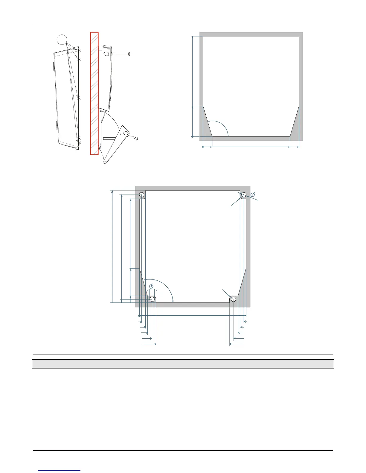
1. Unscrew the 4 frontal screws (Fig. 1, A, B, F, G) and remove the cover (Fig. 1, C).
2. Unscrew the 2 screws (Fig. 1, D, E) that keep connected the frontal and lower parts of Cool Mate and separate the 2 parts.
3. Make the proper holes for cablepresses or pipepresses using the centres signed in the bottom cover of the Cool Mate, (Fig. 3, H, I, ). Then
make 3 holes in the wall, as indicated in (Fig. 3, L, M, N), to fix the Cool Mate
4. Fix the cablepresses and the pipepresses..
5. Insert the wall-nugs, contained in the kit, into the holes made in the wall. Then use the o-rings and fix the back part of the Cool Mate (Fig. 3, L,
M, N) by means of the 3 screws to the wall itself.
6. Insert the wiring cables in cablepresses or in the pipepresses.
7. Mount the frontal part using the previous 4 screws Fig. 1, D, E, F, G. (do not press excessively in order to avoid plastic deformation).
8. After connecting the wires to the terminal blocks close the cover (Fig. 2, c) and fix it by the screws.
 Loading...