dIXEL
Operating Instructions
1592009367
1592009367 XW60LS GB rel.1.0 27.10.06.doc XW60LS 1/4
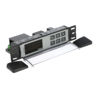
XW60LS
Multifunction digital controller for refrigeration
1. GENERAL WARNING
1.1 PLEASE READ BEFORE USING THIS MANUAL
• This manual is part of the product and should be kept near the instrument for easy and
quick reference.
• The instrument shall not be used for purposes different from those described hereunder. It
cannot be used as a safety device.
• Check the application limits before proceeding.
1.2
SAFETY PRECAUTIONS
• Check the supply voltage is correct before connecting the instrument.
• Do not expose to water or moisture: use the controller only within the operating limits
avoiding sudden temperature changes with high atmospheric humidity to prevent formation
of condensation
• Warning: disconnect all electrical connections before any kind of maintenance.
• Fit the probe where it is not accessible by the End User. The instrument must not be
opened.
• In case of failure or faulty operation send the instrument back to the distributor with a
detailed description of the fault.
• Consider the maximum current which can be applied to each relay (see Technical Data).
• Ensure that the wires for probes, loads and the power supply are separated and far enough
from each other, without crossing or intertwining.
• In case of applications in industrial environments, the use of mains filters (our mod. FT1) in
parallel with inductive loads could be useful.
2. GENERAL DESCRIPTION
Model XW60LS, 38x185 mm format, is microprocessor based controller suitable for applications
on medium or low temperature refrigerating units. It is provided with 3 relay outputs to control
compressor, defrost - which can be either electrical or hot gas - and the evaporator fans.
It is also provided with 2 NTC probe inputs, one for temperature control, one to control the
defrost end temperature of the evaporator. An output allows the user to programme the
parameter list with the “Hot Key”.
3. CONTROLLING LOADS
3.1 THE COMPRESSOR
The regulation is performed according to the temperature measured by the thermostat probe
with a positive differential from the set point: if the temperature increases and reaches set point
plus differential the compressor is started and then turned off when the temperature reaches the
set point value again.
In case of fault in the thermostat probe the start and stop of the compressor are timed through
parameters “COn” and “COF”.
3.2 FAST FREEZING
When defrost is not in progress, it can be activated the keypad by holding the o key pressed
for about 3 seconds. The compressor operates in continuous mode for the time set through the
“CCt” parameter. The cycle can be terminated before the end of the set time using the same
activation key, o for about 3 seconds.
3.3 DEFROST
Two defrost modes are available through the “tdF” parameter: defrost with electrical heater or
hot gas. The defrost interval is control by means of parameter “EdF”: (EdF=in) the defrost is
made every “IdF” time, (EdF=Sd) the interval “IdF” is calculate through Smart Defrost algorithm
(only when the compressor is ON).
3.4 CONTROL OF EVAPORATOR FANS
The fan control mode is selected by means of the “FnC” parameter:
FnC= C-n fans will switch ON and OFF with the compressor and not run during defrost:;
FnC= O-n fans will run continuously, but not during defrost
FnC= C-y fans will switch ON and OFF with the compressor and run during defrost;
FnC= O-y fans will run continuously also during defrost
After defrost, there is a timed fan delay allowing for drip time, set by means of the “Fnd”
parameter.
An additional parameter “FSt” provides the setting of temperature, detected by the evaporator
probe, above which the fans are always OFF. This can be used to make sure circulation of air
only if his temperature is lower than set in “FSt”.
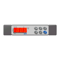
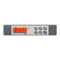
4. THE FRONT FRAME
C
To display and modify target set point; in programming mode it selects a parameter
or confirm an operation.
By holding it pressed for 3s when max or min temperature is displayed it will be
erased.
To see the max. stored temperature; in programming mode it browses the parameter
codes or increases the displayed value. By holding it pressed for 3s the fast freezing
cycle is started.
To see the min stored temperature; in programming mode it browses the parameter
codes or decreases the displayed value.
By holding it pressed for 3s the defrost is started.
Switch ON and OFF the instrument.
KEY COMBINATIONS
+
To lock and unlock the keyboard.
+
To enter the programming mode.
+
To exit the programming mode.
4.1 USE OF LEDS
Each LED function is described in the following table.:
LED MODE Function
ON The compressor is running
FLASHING
- Programming Phase (flashing with LED )
- Anti-short cycle delay enabled
ON The fan is running
FLASHING
Programming Phase (flashing with LED )
ON The defrost is enabled
FLASHING Drip time in progress
ON The Fast Freezing cycle is enabled
ON - ALARM signal
- In “Pr2” indicates that the parameter is also present in “Pr1”
4.2 HOW TO SEE THE MIN TEMPERATURE
1. Press and release the n key.
2. The “Lo” message will be displayed followed by the minimum temperature
recorded.
3. By pressing the n key or waiting for 5s the normal display will be restored.
4.3 HOW TO SEE THE MAX TEMPERATURE
1. Press and release the o key.
2. The “Hi” message will be displayed followed by the maximum temperature
recorded.
3. By pressing the o key or waiting for 5s the normal display will be restored.
4.4 HOW TO RESET THE MAX AND MIN TEMPERATURE RECORDED
To reset the stored temperature, when max or min temperature is displayed :
1. Press SET key until “rST” label starts blinking.
N.B. After the installation RESET the temperature stored .
4.5 HOW TO SEE AND MODIFY THE SET POINT
1. Push and immediately release the SET key: the display will show the Set point
value;
2. The SET LED start blinking;
3. To change the Set value push the o or n arrows within 10s.
4. To memorise the new set point value push the SET key again or wait 10s.
4.6 TO START A MANUAL DEFROST
1. Push the DEF key for more than 2 seconds and a manual defrost will start.
4.7 PER ACCEDERE AI PARAMETRI IN “PR1”
Per entrare nel menu parametri “Pr1” accessibili dall’utente:
1. Enter the Programming mode by pressing the Set and DOWN key for
few seconds.
2. The instrument will show the first parameter present in “Pr1”
4.8 TO ENTER IN PARAMETERS LIST “PR2”
To access parameters in “Pr2”: