dIXEL
Operating Instructions
1592009367
1592009367 XW60LS GB rel.1.0 27.10.06.doc XW60LS 2/4
0. Enter the “Pr1” level.
1. Select “Pr2” parameter and press the “SET” key.
2. The “PAS” flashing message is displayed, shortly followed by “0 - -” with a flashing zero.
3. Use o or n to input the security code in the flashing digit; confirm the figure by pressing
“SET”. The security code is “321“.
4. If the security code is correct the access to “Pr2” is enabled by pressing “SET” on the last
digit.
Another possibility is the following: after switching ON the instrument the user can push Set and
DOWN keys within 30 seconds.
NOTE: each parameter in “Pr2” can be removed or put into “Pr1” (user level) by pressing “SET”
+ n. When a parameter is present in “Pr1” LED is on.
4.9 HOW TO CHANGE THE PARAMETER VALUE
1. Enter the Programming mode.
2. Select the required parameter with o or n.
3. Press the “SET” key to display its value ( and LED starts blinking).
4. Use o or n to change its value.
5. Press “SET” to store the new value and move to the following parameter.
To exit: Press SET + UP or wait 15s without pressing a key.
NOTE: the new programming is stored even when the procedure is exited by waiting the time-
out.
4.10 HOW TO LOCK THE KEYBOARD
Keep the o and n keys pressed together for more than 3 s the o and n keys.
2. The “POF” message will be displayed and the keyboard is locked. At this
point it is only possible the viewing of the set point or the MAX o Min
temperature stored and to switch ON and OFF the light, the auxiliary output
and the instrument.
TO UNLOCK THE KEYBOARD
Keep the o and n keys pressed together for more than 3s.
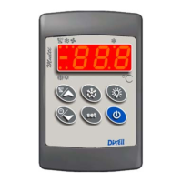
4.11 ON/OFF FUNCTION
By pushing the ON/OFF key, the instrument shows “OFF” for 5 sec. and the
ON/OFF LED is switched ON.
During the OFF status, all the relays are switched OFF and the regulations are
stopped;
N.B. During the OFF status the Light button is active.
4.12 TO SEE THE PROBE VALUES
1. Enter in “Pr2” level.
2. Select “Prd” parameter with o or n.
3. Press the “SET” key to display “Pb1” label alternate with Pb1 value.
4. Use o and n keys to display the other probe values.
5. Press “SET” to move to the following parameter.
5. PARAMETER LIST
REGULATION
Hy Differential: (0,1÷25,5°C; 1÷45°F): Intervention differential for set point, always positive.
Compressor Cut IN is Set Point Plus Differential (Hy). Compressor Cut OUT is when the
temperature reaches the set point.
LS Minimum set point limit: (-50,0°C
÷SET; -58°F÷SET) Sets the minimum acceptable value
for the set point.
US Maximum set point limit: (SET÷110°C; SET÷230°F) Set the maximum acceptable value
for set point.
OdS Outputs activation delay at start up: (0÷255 min) This function is enabled at the initial
start up of the instrument and inhibits any output activation for the period of time set in the
parameter. (Light can work)
AC Anti-short cycle delay: (0÷30 min) interval between the compressor stop and the
following restart.
CCt Thermostat override: (0min ÷23h 50min) allows to set the length of the continuous cycle.
Can be used, for instance, when the room is filled with new products.
Con Compressor ON time with faulty probe: (0÷255 min) time during which the compressor
is active in case of faulty thermostat probe. With COn=0 compressor is always OFF.
COF Compressor OFF time with faulty probe: (0÷255 min) time during which the compressor
is off in case of faulty thermostat probe. With COF=0 compressor is always active.
CH Type of action: CL = cooling; Ht = heating.
DISPLAY
CF Temperature measurement unit: °C = Celsius; °F = Fahrenheit. When the measurement
unit is changed the SET point and the values of some parameters have to be modified.
rES Resolution (for °C): (in = 1°C; de = 0,1°C) allows decimal point display.
dE = 0,1°C; in = 1 °C
Lod Local display : select which probe is displayed by the instrument:
P1 = Thermostat probe
P2 = Evaporator probe
DEFROST
tdF Defrost type:
rE = electrical heater (Compressor OFF)
in = hot gas (Compressor and defrost relays ON)
EdF Defrost mode:
in = interval mode. The defrost starts when the time “Idf” is expired.
Sd = Smartfrost mode. The time IdF (interval between defrosts) is increased only when
the compressor is running (even non consecutively).
SdF Set point for SMARTFROST: (-30÷30 °C/ -22÷86 °F) evaporator temperature which
allows the IdF counting (interval between defrosts) in SMARTFROST mode.
dtE Defrost termination temperature: (-50,0÷110,0°C; -58÷230°F) (Enabled only when the
evaporator probe is present) sets the temperature measured by the evaporator probe which
causes the end of defrost.
IdF Interval between defrosts: (1÷120h) Determines the time interval between the beginning
of two defrost cycles.
MdF (Maximum) duration of defrost: (0÷255 min) When P2P = n, no evaporator probe, it
sets the defrost duration, when P2P = y, defrost end based on temperature, it sets the
maximum length for defrost.
dFd Display during defrost:
rt = real temperature; it = temperature reading at the defrost start;
Set = set point; dEF = “dEF” label; dEG = “dEG” label;
dAd Defrost display time out: (0÷255 min) Sets the maximum time between the end of defrost
and the restarting of the real room temperature display.
dSd Start defrost delay: ( 0÷99min) This is useful when different defrost start times are
necessary to avoid overloading the plant.
Fdt Drain down time: (0÷60 min.) time interval between reaching defrost termination
temperature and the restoring of the control’s normal operation. This time allows the
evaporator to eliminate water drops that might have formed due to defrost.
dPO First defrost after start-up:
y = Immediately; n = after the IdF time
dAF Defrost delay after fast freezing: (0min÷23h 50min) after a Fast Freezing cycle, the first
defrost will be delayed for this time.
FANS
FnC Fan operating mode:
C-n = running with the compressor, OFF during the defrost;
C-y = running with the compressor, ON during the defrost;
O-n = continuous mode, OFF during the defrost;
O-y = continuous mode, ON during the defrost;
Fnd Fan delay after defrost: (0÷255 min) The time interval between the defrost end and
evaporator fans start.
FSt Fan stop temperature: (-50÷110°C; -58÷230°F) setting of temperature, detected by
evaporator probe, above which the fan is always OFF.
ALARMS
ALC Temperature alarm configuration
rE = High and Low alarms related to Set Point
Ab = High and low alarms related to the absolute temperature.
ALU High temperature alarm setting:
ALC= rE, 0 ÷ 50°C or 90°F
ALC= Ab, ALL ÷ 110°C or 230°F
when this temperature is reached and after the ALd delay time the HA alarm is enabled.
ALL Low temperature alarm setting:
ALC = rE , 0 ÷ 50 °C or 90°F
ALC = Ab , - 50°C or -58°F ÷ ALU
when this temperature is reached and after the ALd delay time, the LA alarm is enabled,.
AFH Temperature alarm and fan differential: (0,1÷25,5°C; 1÷45°F) Intervention differential
for temperature alarm set point and fan regulation set point, always positive.
ALd Ritardo allarme temperatura: (0÷255 min) intervallo di tempo tra la rilevazione di un
segnale di allarme temperatura e la sua segnalazione.
dAO Delay of temperature alarm at start-up: (0min÷23h 50min) time interval between the
detection of the temperature alarm condition after the instrument power on and the alarm
signalling.
EdA Alarm delay at the end of defrost: (0÷255 min) Time interval between the detection of the
temperature alarm condition at the end of defrost and the alarm signalling.
PROBE INPUTS
Ot Thermostat probe calibration: (-12.0÷12.0°C/ -21÷21°F) allows to adjust possible offset
of the thermostat probe.
OE Evaporator probe calibration: (-12.0÷12.0°C/ -21÷21°F) allows to adjust possible offsets
of the evaporator probe.
P2P Evaporator probe presence: n= not present: the defrost stops only by time; y= present:
the defrost stops by temperature and time.
OTHER
oA1 Third realy configuration: ALr= alarm; Fan= Fan; Lig = Light; AUS = don’t
use it; OnF = on -off
PbC Type of probe: it allows to set the kind of probe used by the instrument:
PbC = PBC probe, ntC = NTC probe.
rEL Release software: (read only) Software version of the microprocessor.
Ptb Parameter table: (read only) it shows the original code of the dIXEL parameter map.
Prd Probes display: (read only) display the temperature values of the evaporator probe Pb2.
Pr2 Access to the protected parameter list (read only).
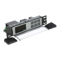
6. INSTALLATION AND MOUNTING
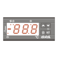
Instruments XW60LS shall be mounted on vertical panel, in a 150x31 mm hole, and fixed using
two screws ∅ 3 x 2mm. To obtain an IP65 protection grade use the front panel rubber gasket
(mod. RG-L). The temperature range allowed for correct operation is 0 - 60 °C. Avoid places
subject to strong vibrations, corrosive gases, excessive dirt or humidity. The same
recommendations apply to probes. Let the air circulate by the cooling holes.
 Loading...