dIXEL
Operating Instructions
1592009367
1592009367 XW60LS GB rel.1.0 27.10.06.doc XW60LS 3/4
6.1 CUT OUT
165
150
31
+0.5
-0
+0.5
-0
+1
-1
Ø3 x2
6.2 MOUNTING WITH KEYBOARD COVER OPENING UPWARD
CLICK!
1
2
2
3
3
1
1
6.3 MONTAGGIO VETRINO E CALOTTE FRONTALI CON APERTURA VERSO L’ALTO
CLICK!
1
2
2
2
3
3
1
1
7. ELECTRICAL CONNECTIONS
The instrument is provided with faston 2.8mm for analogue inputs. Relays and power supply
have a Faston connection (6,3mm). Heat-resistant cables have to be used. Before connecting
cables make sure the power supply complies with the instrument’s requirements. Separate the
probe cables from the power supply cables, from the outputs and the power connections. Do not
exceed the maximum current allowed on each relay, in case of heavier loads use a suitable
external relay.
N.B. Maximum current allowed for all the loads is 20A.
7.1 PROBE CONNECTIONS
The probe shall be mounted with the bulb upwards to prevent damages due to casual liquid
infiltration. It is recommended to place the thermostat probe away from air streams to correctly
measure the average room temperature.
8. USE OF THE PROGRAMMING “HOT KEY “
The Wing units can UPLOAD or DOWNLOAD the parameter list from its own E2 internal
memory to the “Hot Key” and vice-versa.
8.1 DOWNLOAD (FROM THE “HOT KEY” TO THE INSTRUMENT)
1. Turn OFF the instrument by means of the ON/OFF key, remove the TTL serial cable if
present, insert the “Hot Key” and then turn the Wing ON.
2. Automatically the parameter list of the “Hot Key” is downloaded into the Wing memory,
the “DoL” message is blinking. After 10 seconds the instrument will restart working with
the new parameters.
3. Turn OFF the instrument remove the “Hot Key”, plug in the TTL serial cable, then turn it
ON again.
At the end of the data transfer phase the instrument displays the following messages:
“end “ for right programming. The instrument starts regularly with the new programming.
“err” for failed programming. In this case turn the unit off and then on if you want to restart the
download again or remove the “Hot key” to abort the operation.
8.2 UPLOAD (FROM THE INSTRUMENT TO THE “HOT KEY”)
1. Turn OFF the instrument by means of the ON/OFF key and remove the TTL serial cable if
present; then turn it ON again.
2. When the Wing unit is ON, insert the “Hot key” and push o key; the "uPL" message
appears.
3. Push “SET” key to start the UPLOAD; the “uPL” message is blinking.
4. Turn OFF the instrument remove the “Hot Key”, plug in the TTL serial cable, then turn it
ON again.
At the end of the data transfer phase the instrument displays the following messages:
“end “ for right programming.
“err” for failed programming. In this case push “SET” key if you want to restart the programming
again or remove the not programmed “Hot key”.
9. ALARM SIGNALS
Mess. Cause Outputs
“P1” Thermostat probe failure Alarm output ON; Compressor output according to
parameters “COn” and “COF”
“P2” Evaporator probe failure Alarm output ON; Other outputs unchanged
“HA” Maximum temperature alarm Alarm output ON; Other outputs unchanged
“LA” Minimum temperature alarm Alarm output ON; Other outputs unchanged
“EE” Data or memory failure
The alarm message is displayed until the alarm condition is recovery.
All the alarm messages are showed alternating with the room temperature except for the “P1”
which is flashing. To reset the “EE” alarm and restart the normal functioning press any key, the
“rSt” message is displayed for about 3s.
9.1 “EE” ALARM
The dIXEL instruments are provided with an internal check for the data integrity. Alarm “EE”
flashes when a failure in the memory data occurs. In such cases the alarm output is enabled.
9.2 ALARM RECOVERY
Probe alarms : “P1” (probe1 faulty), “P2” ; they automatically stop 10s after the probe restarts
normal operation. Check connections before replacing the probe.
Temperature alarms “HA” and “LA” automatically stop as soon as the thermostat temperature
returns to normal values or when the defrost starts.
10. TECHNICAL DATA
Housing: self extinguishing ABS.
Case: facia 38x185 mm; depth 48mm
Mounting : panel mounting in a 150x31 mm panel cut-out with two screws. ∅ 3 x 2mm.
Distance between the holes 165mm
Protection: IP20.
Frontal protection: IP65 with frontal gasket mod RG-L. (optional)
Connections: Faston 2,8mm heat-resistant wiring for probes, heat-resistant wiring and 6,3mm
Faston for loads and power supply
Power supply: 230Vac or. 110Vac ± 10%
Power absorption: 3VA max.
Display: 3 digits, red LED, 14,2 mm high.
Inputs: 2 NTC probes
Relay outputs: Total current on loads MAX. 20A
compressor: relay SPST 20(8) A, 250Vac
defrost: relay SPST 8(3) A, 250Vac
fans: relay SPST 8(3) A, 250Vac
Data storing: on the non-volatile memory (EEPROM).
Kind of action: 1B.
Pollution grade: normal
Software class: A.
Operating temperature: 0÷60 °C.
Storage temperature: -25÷60 °C.
Relative humidity: 20÷85% (no condensing)
Measuring and regulation range:
NTC probe: -40÷110°C (-58÷230°F)
Resolution: 0,1 °C or 1°C or 1 °F (selectable).
Accuracy (ambient temp. 25°C): ±0,5 °C ±1 digit
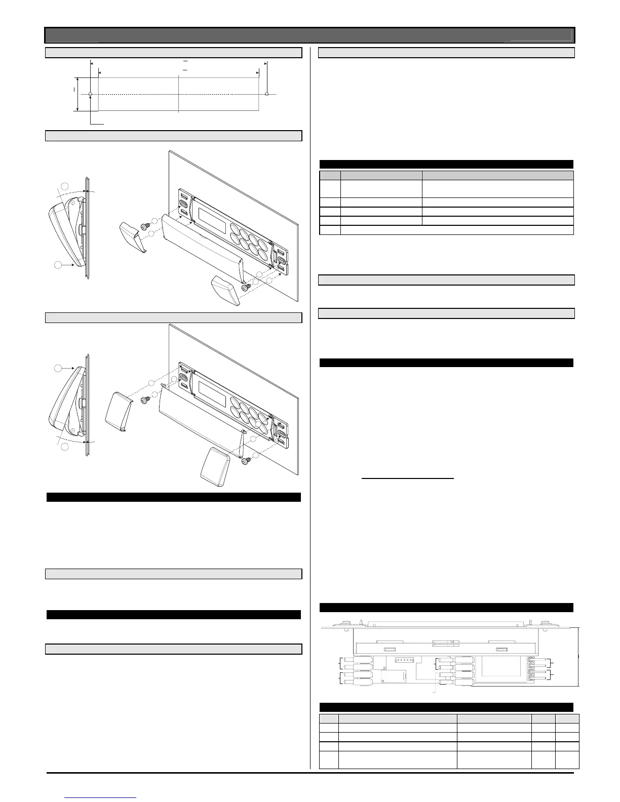
11. CONNECTIONS
Defrost
Fan
RL2
RL3
Power
230V
Compr.
RL1
TRF
Room
Probe
Evaporator
Probe
48
12. DEFAULT SETTING VALUES
Label Nome Limiti Valore Livello
REGULATION
Set Set point LS÷US -5.0 Pr1
Hy Differential 0,1÷25,5 °C / 1÷45°F
2.0 Pr1
LS Minimum set point -50,0°C÷SET / -
58°F÷SET
-30.0 Pr2
 Loading...