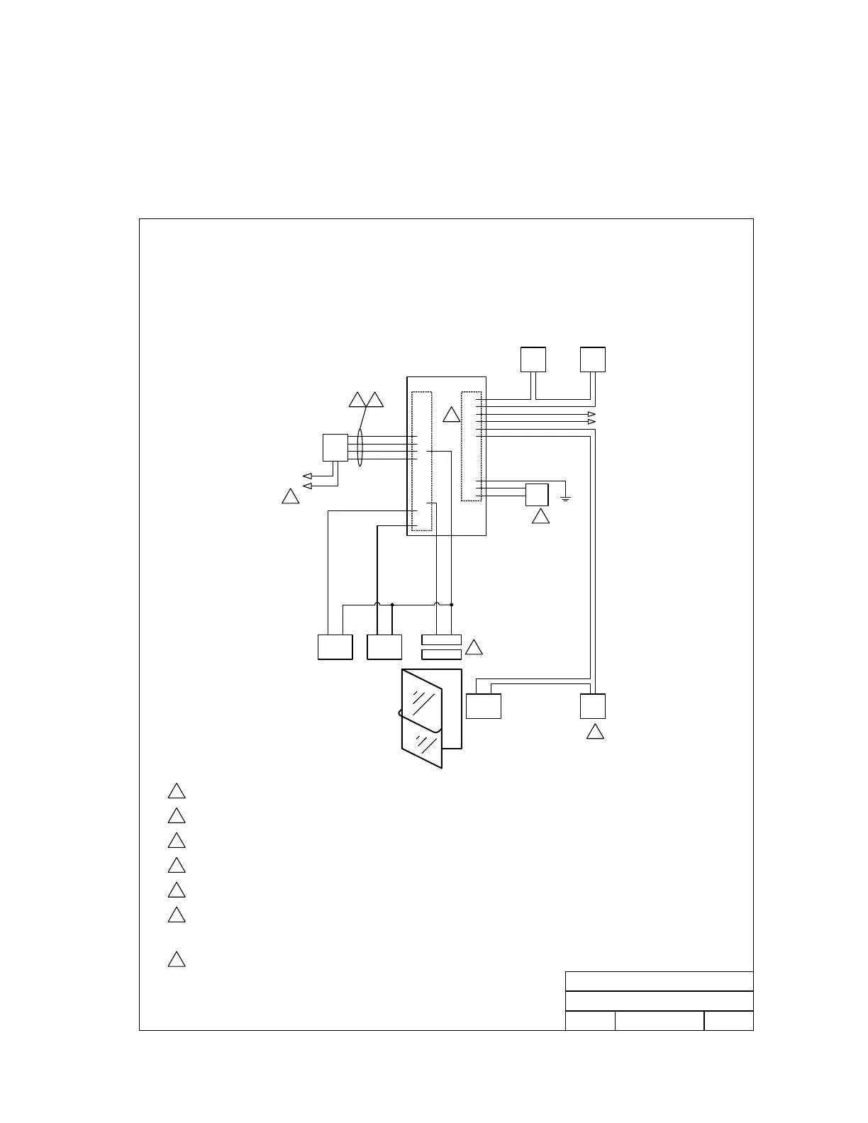
3.6 Door Control Wiring Detail - Typical
• Set output relay shorting bar on the Tracker board to N.O. (Normally Open) when using fail-
secure (electric strikes) locking devices; set to N.C. (Normally Closed) when using fail-safe
(magnetic locks) locking devices.
2351-010 Expansion Board Door Control
Detail Wiring
1
2
3
4
5
6
7
8
9
10
11
12
13
14
1
2
3
4
5
6
7
8
9
10
11
12
13
14
15
16
17
18
STRIKE /
MAG LCK
DOOR SW
MAGNET
LCK
PWR
ALARM
PWR
LOCAL
ALARM
EXIT
REQUEST
ALARM
RESET
Dry relay contacts
connect to alarm system.
2
1
3
4
CARD
RDR
GRN
WHT
BLK
RED
5
PWR
INPUT
GND
16 VAC
16 VAC
P2 P1
Detail Wiring - 2351-010 Expansion Board
Door Control
DOORKING, INC., INGLEWOOD, CA 90301
Title:
Date: Rev.Dwg. No.
6
3/03
B
M2351-065-11
Light
Power
16 Volt, 20 VA UL Listed.
Power for door strikes or magnetic lock is not provided by the
system. It must be provided by an external power supply.
Switch is wired N.C. (Normally Closed).
Relay contacts (1-2; 3-4; 5-6) are rated at 5A 250V maximum and can
be set for Normally Open (N.O.) or Normally Closed (N.C.) operation.
Belden 9418 or equivalent.
Green = Data 0
White = Data 1
Black = Common
Red = 12 VDC Power
1
2
3
4
5
6
7
7
If card reader is lighted, separate light power must be provided.
NOTE: Wiring to controller/other tracker boards is not shown.
2351-065-G-12-07 Page 31