Table of Contents
Section 1 – Setup
1.1 General Information..................................................................................................................................7
1.2 Tracker Board Input / Output Descriptions
1.2.1 Access Control Device (Weigand) Input ..................................................................................8
1.2.2 Gate Operator Data Input.........................................................................................................8
1.2.3 Request to Exit Input................................................................................................................8
1.2.4 Door Ajar Input .........................................................................................................................8
1.2.5 Reset Alarm Input ....................................................................................................................8
1.2.6 Command Relay Input .............................................................................................................9
1.2.7 Monitor and Alarm Relays........................................................................................................9
1.2.8 Output Relay ............................................................................................................................9
1.2.9 Weigand Output .......................................................................................................................9
Board Setting Locations...........................................................................................................10
1.3 Monitor and Alarm Relay Operation
1.3.1 Mode-1 .....................................................................................................................................11
1.3.2 Mode-2 .....................................................................................................................................12
1.4 Hold Open Features
1.4.1 Hold Open Time Zones............................................................................................................14
1.4.2 Hold Open Override .................................................................................................................14
1.5 Board and Relay Identification
1.5.1 Board Identification ..................................................................................................................15
1.5.2 Relay Identification...................................................................................................................16
40 and 50 Series Control Boards.............................................................................................17
30 Series Control Boards.........................................................................................................18
1.5.3 Terminal Identification..............................................................................................................19
Section 2 – Installation
General Information..................................................................................................................................................21
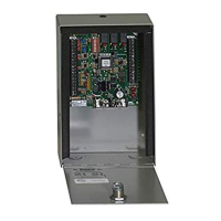
2.1 Single Housing .........................................................................................................................................22
2.2 Quad Housing...........................................................................................................................................23
Section 3 – Wiring Information
Block Diagram ..........................................................................................................................................................25
3.1 Tracker Boards 1-8 Detail Wiring for 40 and 50 Series Control Boards...................................................26
3.2 Tracker Boards 9-16 Detail Wiring for 40 Series Control Boards.............................................................27
3.3 Tracker Boards 1-8 Detail Wiring for 30 Series Control Boards...............................................................28
3.4 Tracker Boards 9-16 Detail Wiring for 30 Series Control Boards.............................................................29
3.5 Block Diagram Single Door Control..........................................................................................................30
3.6 Door Control Wiring..................................................................................................................................31
3.7 Gate Operator Data..................................................................................................................................32
3.8 General Wiring Information ......................................................................................................................34
Section 4 – Trouble Shooting
4.1 LED Identification .....................................................................................................................................35
4.2 Weigand Device Data...............................................................................................................................36
4.3 Gate Operator Data..................................................................................................................................37
Gate Operator Event Report ....................................................................................................................38
2351-065-G-12-07 Page 5