DMN-WESTINGHOUSE AL-BL Rotary Valves
Code: AL-E.B.01.B 11-2012
22
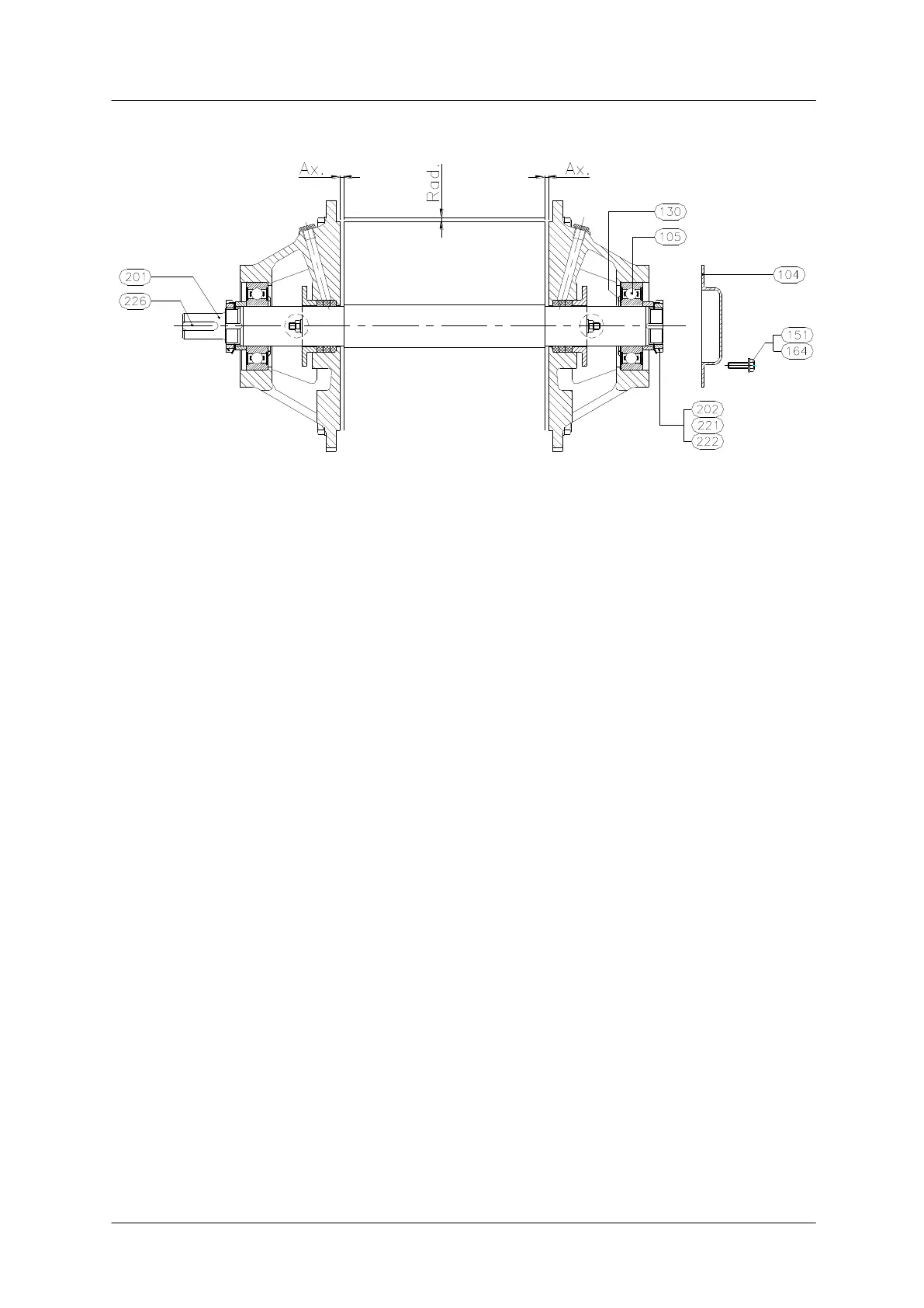
Rotor with fixed blades
Fig. 3.1.4.3.1 Adjustment for axial clearance.
The rotor must be adjusted in axial direction (at both sides) with a tolerance between
the machined surfaces of the rotor.
- Push the rotor hard against the inside face of the end cover at the non-drive
end.
- Measure the total end clearance. Equalise this clearance by placing a feeler
gauge between the vane and the non-drive end cover.
- Tighten locknut until the gauge is just nipped in position.
- Secure the locknut.
- Now tighten the locknut at the drive end until the feeler gauge can be removed.
- Secure drive end locknut and check that both end clearances are equal.
Rotor with adjustable blades
Adjustment of axial rotor as described under rotor with fixed blades.
Axial/radial adjustment of the rotor blades:
The tolerances for the axial adjustment of the rotor blades are the same as stated
for the rotor.
The radial clearance should normally be between 0.12-0.17 mm (see table page 21)
but it is preferable to try and achieve a smallest possible clearance (i.e. 0.12-0.15
mm).
Feeler gauges or copper shims of the correct thickness should be used for adjusting
clearances. They are placed between the loose rotor blades and the cylindrical wall
of the body. (i.e. adjacent to the inlet opening and as close to the end covers as
possible).