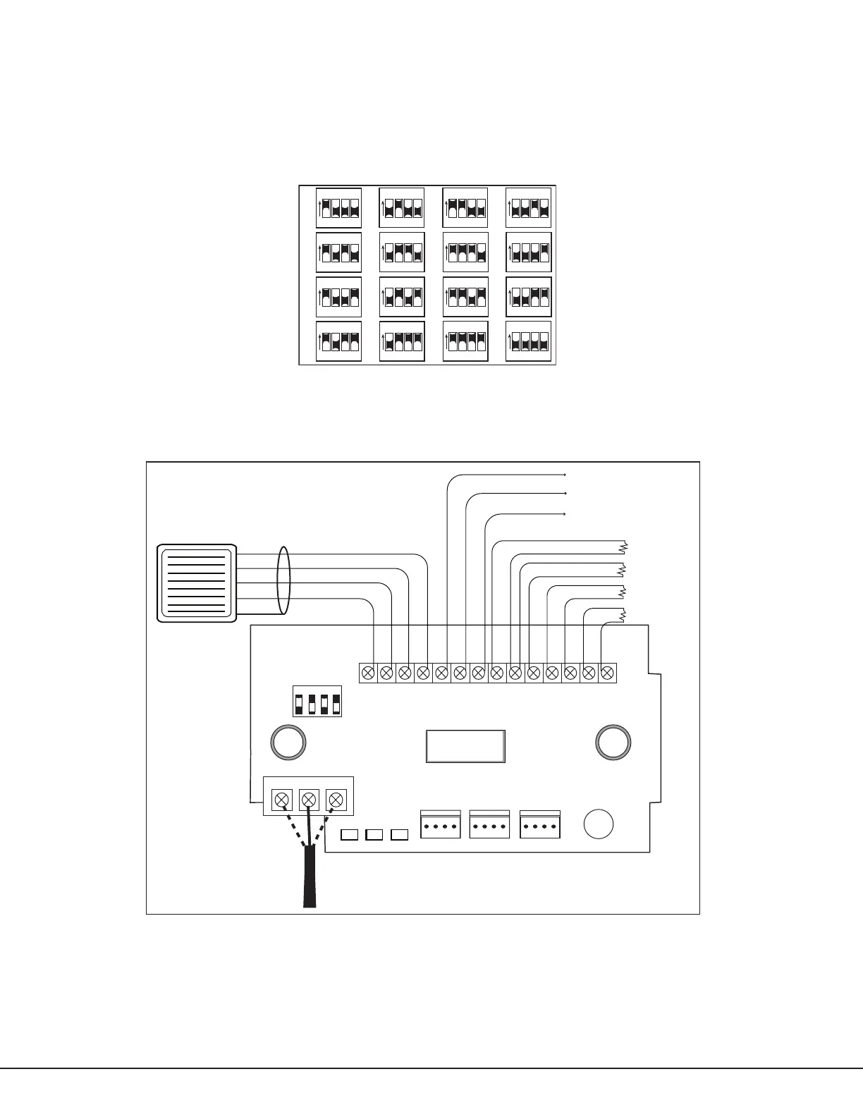
Set the 734 Module Address
The 734 is a supervised module and cannot operate in unsupervised mode. To change the current address, refer to
Figure 2 and move the slide switches to the appropriate address positions.
• XRSuper6 and XR20 panels use addresses 1 to 4 and automatically recognize the switch setting
• The XR40 use addresses 1 to 8 and automatically recognize the switch setting
• XR100 Series use addresses from 1 to 8 in panel programming Device Setup
• XR500 Series and XR2500F use addresses from 1 to 16 in panel programming Device Setup.
ON
1 2 3 4
ON
1 2 3 4
ON
1 2 3 4
ON
1 2 3 4
ON
1 2 3 4
ON
1 2 3 4
ON
1 2 3 4
ON
1 2 3 4
ON
1 2 3 4
ON
1 2 3 4
ON
1 2 3 4
ON
1 2 3 4
ON
1 2 3 4
ON
1 2 3 4
ON
1 2 3 4
ON
1 2 3 4
1 2 3 4
5 6 7 8
9 10 11 12
13 14 15 16
Figure 2: 734 Addresses
734 Module Wiring
The 734 connects to the keypad data bus and a Wiegand format reader. Refer to Figures 3, 4, and 5 and the
instructions in this guide for proper wiring.
RED
PROG
J2
734
Interface
Module
1
2
3
4567
8
10
11 12 13 14
9
LC ASRED WHTGRN BLKZ1Z2Z3 Z4+ Z4–RA GND GND
RED
J5
RED
KYPD IN
J4
KYPD OUT
S1
J3
J1
DATA
XMT LED
WIEGAND
READ LED
RELAY
ON
NC CNO
GRNYELRED
+ –
ON
Piezo
Model 333
Supressor
Card Reader
Red
White (Data 1)
Black
Green (Data 0)
Note: Only use shielded wire if specified by the reader
manufacturer. Only connect the shield to the reader.
Refer to reader installation documentation for more
information.
Shield
Remote Audible Annunciator
Armed Status Output
Remote LED Control
Zone 1
Zone 2
Zone 3
Zone 4
Note: Use 1K Ohm EOL for each zone.
D
a
t
a
1
D
a
t
a
0
+
12
V
D
C
G
N
D
Maximum line impedance is 100 Ohms
Zone 4 Ground fault detected at 1420 Ohms or less
Normal operating range is 650 - 1200 Ohms
Figure 3: 734 Wiring Diagram
Card Reader
Figure 3 shows a reader with wire colors Red, White, Green, and Black. The wire colors may be different for the
reader being installed. Connect the reader wires to J3 terminals 1, 2, 3, and 4. As shown in Figure 3, the Green
wire carries D0, or Data Zero, and the White wire carries D1, or Data One. The Red wire carries 12 VDC output and
the Black wire is ground. Refer to the literature provided with the reader for wire coding, wire distance, cable type
(such as shielded), and other specications. If you are powering the readers from an auxiliary power source, refer
to 12 VDC Access Control Readers later in this document.
Digital Monitoring Products 734 Installation and Programming Guide
2