Digital Monitoring Products 734N Installation Guide
4
Reset Header
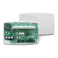
The reset header is located just above and to the right of the network connector (see Figure 1) and is used to reset the
734N module. To reset the module when rst installing the system, short the two pins on the reset header before applying
power to the module.
To reset the module while the system is operational, short the two pins on the reset header for one or two seconds without
powering down the system.
Addressing the 734N
Keypad Bus Addresses
DMP XR550 Series panels use keypad bus addresses 2 through 16. XR150 Series panels can only use keypad bus addresses 2
through 8. Address 1 is reserved for hardwired keypads on both XR150 and XR550 Series panels. Each keypad bus address
can accommodate 1 door output and 4 expansion zones. The 734N operates using addresses 2-16, with address 1 being
reserved for panel keypad operation. A 734N with an address of 2 on the keypad bus would represent Door 2 and zones 21-
24. A 734N with a keypad address of 14 would represent Door 14 and zones 141-144.
AX-Bus Addresses (XR550 only)
DMP XR550 panels are capable of access control expansion using any of the ve AX/LX-Bus headers (AX/LX500, 600, 700,
800, and 900). An AX-Bus address can accommodate 1 door output and 1 expansion zone. Because the 734N has a built-in
4-zone expander, 3 extra zones must be mapped to the 734. A 734N with an address of 501 on AX500 would represent Door
501 and zones 501-504. A 734N with an address of 505 on AX500 would represent Door 505 and zones 505-508. A 734N with
an address of 701 on AX700 would represent Door 701 and zones 701-704.
Note: Hardwired zone expanders and addressable points and modules do not communicate on an AX-Bus. AX-Bus doors do
not have programmable device or communication types and do not have assignable display areas.
Setting the 734N Addresses
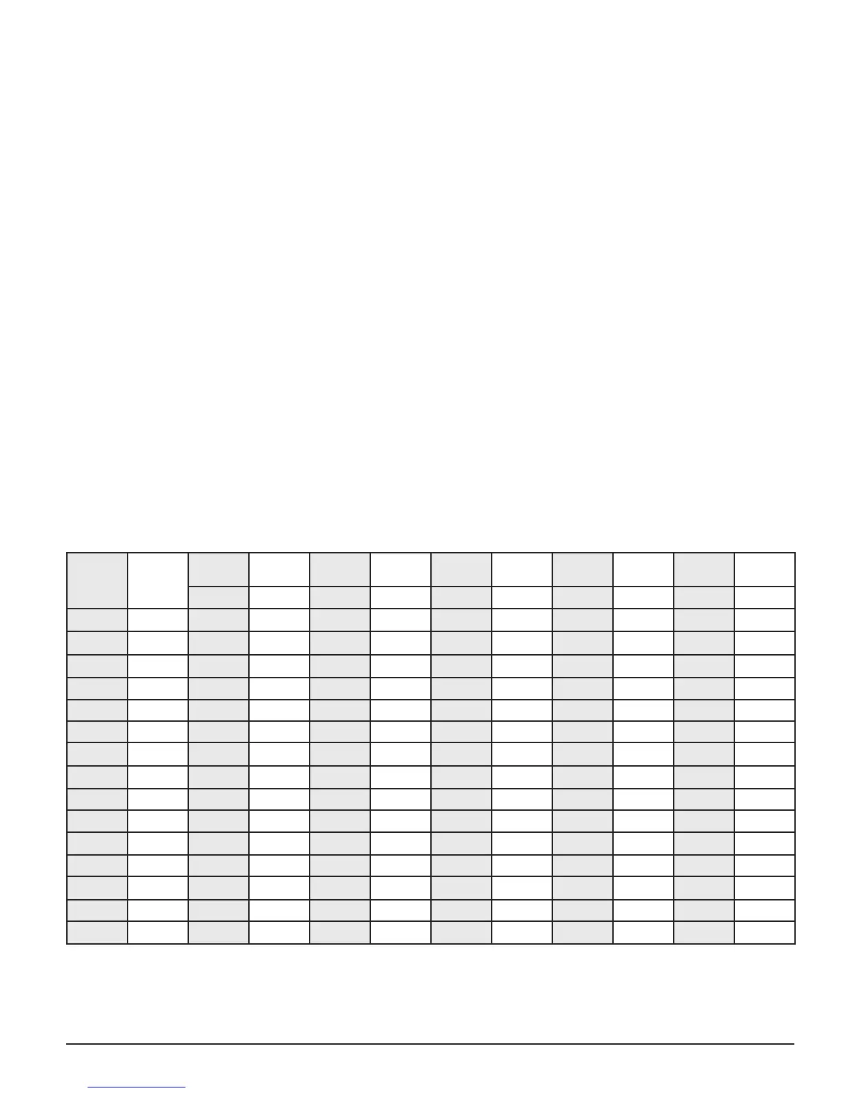
To set the 734N address, refer to Table 2.
Only valid door numbers can be assigned to 734Ns in device setup. For complete keypad and AX-Bus address mapping, see
the chart below.
Table 2: Device Addresses and 734N Zone Numbers
Device/
Door
Zones
Device/
Door
Zones
Device/
Door
Zones
Device/
Door
Zones
Device/
Door
Zones
Device/
Door
Zones
501 501-504 601 601-604 701 701-704 801 801-804 901 901-904
2 21-24 505 505-508 605 605-608 705 705-708 805 805-808 905 905-908
3 31-34 509 509-512 609 609-612 709 709-712 809 809-812 909 909-512
4 41-44 513 513-516 613 613-616 713 713-716 813 813-816 913 913-916
5 51-54 517 517-520 617 617-620 717 717-720 817 817-820 917 917-920
6 61-64 521 521-524 621 621-624 721 721-724 821 821-824 921 921-924
7 71-74 525 525-528 625 625-628 725 725-728 825 825-828 925 925-928
8 81-84 529 529-532 629 629-632 729 729-732 829 829-832 929 929-932
9 91-94 533 533-536 633 633-636 733 733-736 833 833-836 933 933-936
10 101-104 537 537-540 637 637-640 737 737-740 837 837-840 937 937-940
11 111-114 541 541-544 641 641-644 741 741-744 841 841-844 941 941-944
12 121-124 545 545-548 645 645-648 745 745-748 845 845-848 945 945-948
13 131-134 549 549-552 649 649-652 749 749-752 849 849-852 949 949-952
14 141-144 553 553-556 653 653-656 753 753-756 853 853-856 953 953-956
15 151-154 557 557-560 657 657-660 757 757-760 857 857-860 957 957-960
16 161-164 561 561-564 661 661-664 761 761-764 861 861-864 961 961-964
Note: The 734N is a supervised module and cannot operate in unsupervised mode.