XR150/550 LAB GUIDE
Instructor-Led Training
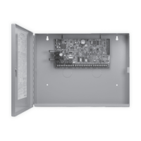
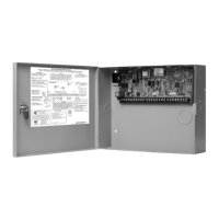
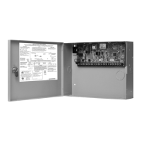
IDENTIFY PANEL COMPONENTS
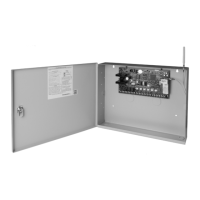
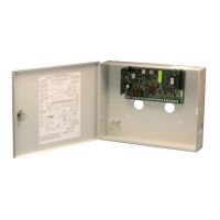
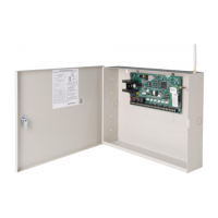
1. Identify the following panel components using the
panels in front of you, or the on-screen photo of the
XR.
ê Reset header
ê Programming
header
ê Outputs
ê AC Power terminals
ê Cellular pins
ê 1100 Series antenna
connection
ê On-board zone
terminals
ê Network connection
ê EXP header
POWER UP THE CONTROL PANEL
1. Connect AC power to terminals 1 & 2
ê Transformer type: 16.5VAC 50VA
2. Connect battery backup to terminals 3 & 4
3. Connect alarm bell to terminals 5 & 6
ê Normal 12VDC is supplied to terminal 5, terminal 6 is ground reference
ê 1/2 W 1K Ohm resistor should be added across the bell circuit for supervision
ENTER PANEL PROGRAMMER
1. Reset the panel using the RESET JUMPER
2. Enter 6653 (PROG) and press CMD
3. Press CMD to navigate through the panel programmer
menus:
ê Initialization
ê Communication
ê Network Options
ê Messaging Setup
ê Device Setup
ê Remote Options
ê System Reports
ê System Options
ê Bell Options
ê Output Options
ê Output Information
ê Output Groups
ê Status List
ê Menu Display
ê PC Log Reports
ê Area Information
ê Zone Information
ê Stop
ê Set Lockout Code
ê Feature Upgrade
ADJUST COMMUNICATION TYPE
1. Navigate to COMMUNICATION and press a top-row
select area
2. Press a top-row select area to clear the default
ACCOUNT NUMBER
3. Enter in an ACCOUNT NUMBER
4. Press CMD to navigate to PATH
5. Press 1 to program PATH 1
6. Press a top-row select area to display the
COMMUNICATION types
7. Select NET
8. Press CMD to navigate to RECEIVER IP
9. Press a top-row select area and enter in the DMP Tech
Support receiver IP Address
ê 209.248.148.051 (Port 2001)
10. Press CMD to exit COMMUNICATION
ADD A KEYPAD
1. Navigate to DEVICE SETUP and press a top-row
select area
2. Enter a DEVICE NUMBER and press CMD
ê The valid range for an XR150 panel is 1-8, XR550 is 1-16
3. Press a top-row select area and enter a DEVICE NAME
4. Press CMD to confirm the DEVICE TYPE
5. Press CMD to exit DEVICE SETUP
ADJUST THE KEYPAD ADDRESS
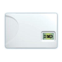
GRAPHIC TOUCHSCREEN KEYPAD
1. Select OPTIONS from the carousel
2. Select the INSTALLER OPTIONS icon
3. Enter 3577 (INST) and press CMD
4. Select KEYPAD OPTIONS (KPT OPT)
5. Press a top-row select area and enter a new
keypad address
6. Press CMD to exit Keypad Options
7. Select STOP to save keypad programming
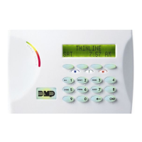
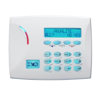
THINLINE KEYPAD
1. Press and hold the BACK ARROW and CMD for 2
seconds
2. Enter 3577 (INST) and CMD
3. Select KEYPAD OPTIONS (KPD OPT)
4. Press a top-row select area or key to change the
keypad address
5. Press CMD to exit KEYPAD OPTIONS
6. Select STOP to save keypad programming
CONFIGURE SYSTEM OPTIONS
1. Navigate to SYSTEM OPTIONS and press a top-row
select area
2. Press CMD to navigate to ENTRY DELAY 1
3. Press a top-row select area and choose a time from
30 to 250 seconds
4. Repeat this process for ENTRY DELAY 2
5. Press CMD to navigate to HOURS FROM GMT
6. Press a top-row select area, enter in the hours from
GMT for your location and press CMD
7. Using CMD, navigate to HOUSE CODE
8. Press a top-row select area and enter a house code
from 1-50 and press CMD
9. Using CMD, navigate to ENTER WEATHER ZIP CODE
10. Press a top-row select area and enter a local ZIP code
to display weather alerts on the keypad
©2021 Digital Monitoring Products, Inc. | 21041 | LT-2351©2021 Digital Monitoring Products, Inc. | 21041 | LT-2351




 Loading...