XT SERIES WIRELESS INSTALLATION QUICK START GUIDE
LT-1289 20171 © 2020 Digital Monitoring Products, Inc.
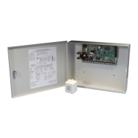
2. INSTALL THE ENCLOSURE
Select a Location
Choose a location that is away from metal and electrical equipment. If
you choose to use the XT50 with built-in wireless receiver make sure to
locate the control panel where the receiver will have a clear path between
the panel and wireless transmitters. Do not place the panel with built-in
receiver in an area where the receiver will have poor signal reception from
the wireless transmitters. Make sure to walk test and survey the system
prior to mounting the control panel.
Mount the Enclosure
Prior to mounting and as needed, open any enclosure knockouts. Mount
the 340 or 349 Enclosure in a secure, dry place to protect the components
from damage due to tampering or the elements. It is not necessary to
remove the pre-mounted components when installing the enclosure. Make
sure all wiring in the XT30 or XT50 Control Panel Enclosure is routed
neatly and securely to keep the wiring o of the panel and power supply
components.
3. BATTERY CONNECTION
The control panel comes with a red and black battery harness. Connect the
positive (red) battery lead to terminal 3 and the negative (black) battery
lead to terminal 4. Do not reverse polarity as this will cause panel damage.
Terminal 4 is also used for the panels Cold Water Earth Ground.
Caution: Observe polarity.
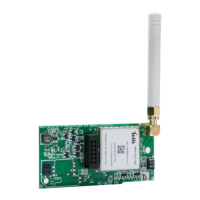
4. CONNECT WIRELESS ANTENNA TO PANEL
The XT50 Wireless Antenna terminal block is located at the top right corner
of the circuit board. The antenna installs through a small opening in the top
of the enclosure and is attached to the panel using the right terminal. The
left terminal is not used.
1. SYSTEM INFORMATION
Before installing any equipment, complete the following section.
Account Number _____________________________________________
Address ____________________________________________________
Phone Number _______________________________________________
Panel IP Address ______________________________________________
Gateway IP Address ___________________________________________
Subnet Mask _________________________________________________
Programming Port ____________________________________________
Installation Date ______________________________________________
SYSTEM COMPONENTS
The system package includes the following components:
• One XT30 or XT50 Control Panel with 340 or 349 enclosure
• One 40 VA Transformer
• 7060 LCD Keypad
• One 1100D series wireless receiver or internal wireless receiver of the XT50
• 1100 Series wireless Transmitters
• If needed 1100R–W Wireless Repeater
• At least one 12 VDC 7 Ah System Battery
REFERENCE INFORMATION
System Grounding
Connect a 14 AWG or larger wire from XT30 or XT50 panel terminal 4 to
a Cold Water Grounding Block. Do not connect to an electrical ground,
conduit, sprinkler or gas pipes, or to a telephone company ground. Do not
connect AC ground to this grounding block.
System Wiring
All wiring must be in accordance with NEC, ANSI, and NFPA 70. Use
non-shielded 22 AWG wire for short wire runs from the panel. Use
non-shielded 18 AWG wire for longer wire runs from the panel. It is
recommended that strain reliefs be used in all locations where wires exit an
enclosure and conduit is not used.
Reference Documents
As needed during installation, refer to the included wiring diagrams, any
documents included with the system components, the XT30/XT50 Series
Installation Guide (LT-0980), XT30/XT50 Series Programming Guide
(LT-0981), 505-12 Installation (LT-0453), 7060 Keypad Installation
(LT-0883), 1100D Installation (LT-0692), and any documentation included
with the system components.
Current Draw
Combined current draw from Auxiliary (Terminal 7), Smoke (Terminal 11)
must not exceed 500 mA in order to support powered devices powered by
the control panel. A separate power supply is needed to support devices
beyond 500 mA. Use the 505-12 DC output J6 for additional auxiliary
powered devices up to a maximum of 5 A.
Outputs
1
2
3
4
Reset
1100 Series
Wireless Antenna
connection
Cellular
header
65555
Built-in Cellular
Module
Connect
antenna to
right side
only
Load
1100 Series
Antenna
(XT50)
TX RX
Wireless LEDs
Figure 1: Wireless Antenna
5. INSTALL AN EXTERNAL 1100D WIRELESS RECEIVER
Select a Location
Choose an optimum location to mount the receiver. The 1100D Wireless
Receiver is typically mounted at a distance not to exceed 500 feet away
from the panel enclosure (use 18 AWG 4 conductor non-shielded wire).
A location should be selected that will be centrally located between the
1100 Series transmitters used in the installation. Install the receiver away
from large metal objects. Mounting the receiver on or near metal surfaces
impairs performance. When selecting the proper mounting location and
operation, refer to the LED Survey Operation section of the specific
installation guide for the transmitter being installed.
Mount the Receiver
Caution: Remove all AC and battery power from the panel before
installing or connecting any modules, cards, or wires.
1. Squeeze both sides of the device to gently separate the cover from
the base.
2. Secure the receiver to the wall in the desired location installing the
supplied screws in the mounting hole locations as shown in Figure 2.
3. Snap the cover back on the unit. The panel immediately recognizes
the 1100D Receiver if the panel is programmed with a house code.
RYGB
TO PANEL
Mounting Holes
Squeeze to
Remove Cover
Squeeze to
Remove Cover
Figure 2: 1100D Series Mounting Holes