LT-1289 20171 © 2020 Digital Monitoring Products, Inc.
Conduct the Walk Test
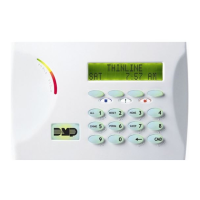
Reset the control panel by momentarily placing a jumper on J16 then wait
one minute. From the keypad, enter the code 8144. The keypad displays
WALK TEST. If the system is monitored and the communication type is DD
or NET, the system sends a System Test Begin report to the central station.
All programmed zones are included in the test.
• STD (Standard Walk Test) - Select STD to Walk test zones. All
programmed zones are included in the test.
• WLS (Wireless Check-in Test) - Select WLS to automatically test
1100 Series wireless transmitter communications. Includes all
wireless devices except key fobs and transmitters programmed for a
supervision time of 0 (zero).
Note: For the XT30, Wireless Check-in Test operation only displays
when connected to 1100D Wireless Receiver Version 105 or higher.
• PIR (Wireless PIR Walk Test) - The PIR Walk Test allows the installer
to verify the 1126 operation. When enabled, the 1126 LED flashes each
time motion is detected for up to 30 minutes. This is a local test only
and no messages are sent to the Central Station.
Trip Counter for Walk Test (STD)
Displays the number of zone trips during the Walk Test.
• Each time a selected zone trips, the keypad buzzes and the bell
rings for two seconds.
• Each time a FI, FV, or SV zone trips, a Sensor Reset occurs.
END - Press the Select key directly below END to stop the Walk Test.
When the Walk Test ends or a 20 minute time-out expires, a final Sensor
Reset occurs. The System Test End message is sent to the receiver along
with Verify and Fail messages for each zone under test. Faulted zones
then display on the keypad.
Trip Counter For DMP Wireless Check-in Test (WLS)
Displays the number of wireless zones that automatically communicate a
supervisory check-in message.
• The number of zones that check in. (XX in the example).
• The total number of wireless zones programmed for supervision
that should check in. (ZZ in the example).
END - Select END to stop the Wireless Check-in Test. When the test
ends or a 20-minute time-out expires, normal wireless zone processing
returns. If all transmitters check-in, both numbers will match within three
minutes. If a transmitter has multiple zones (1101, 1114, etc.), all zones will
be included in the counts. Failed wireless zones will then display on the
keypad.
9. COMPLETE INSTALLATION
After system power-up, perform the following steps to set the panel up for
remote programming.
1. Reset the panel using the reset jumper. Remove the jumper and store
it on one J16 pin for future use.
2. At the 7060 Keypad set to Address #1, enter 6653 and press CMD.
3. At the INITIALIZATION menu press any top row Select key.
4. Answer YES to all Initialization options.
5. Panel is now ready to be programmed. See panel programming
guide.
6. Press CMD until STOP displays.
Note: The information entered is NOT SAVED until you run the STOP
routine.
7. At the STOP menu press any top row Select key to save the
programming.
8. The system is now ready to program using Remote Link™
10. CONNECT THE TRANSFORMER AND AC POWER
Do not plug power cord into dedicated outlet not controlled by a switch
until all devides are connected to the panel.
Note: Never share the transformer output with any other equipment
11. ZONE LAYOUT
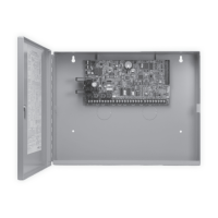
Zones 1-10 are located directly on the XT30/XT50 Control Panel. Zones 1
through 9 each terminate with 1k Ohm EOL resistors. Zone 10 terminates
with 3.3k Ohm EOL resistors.
12. WIRING
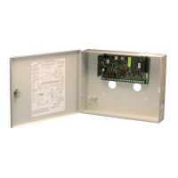
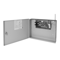
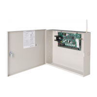
See Figures 6 and 7 that illustrate the XT30/XT50 wireless wiring details.
13. WALK TEST
About the Walk Test
The XT30/XT50 panel provides a walk test feature that allows a single
technician to test all the protection devices connected to zones on the
system. Conduct the Walk Test within 30 minutes of resetting the panel.
The Walk Test automatically ends if no zones are tripped for 20 minutes.
TEST IN PROGRESS displays at all keypads. When five minutes remain,
TEST END WARNING displays. If any areas are armed the Walk Test does
not start and SYSTEM ARMED displays.
Test End Warning
When no zones have been tripped and five minutes remain on the 20
minute Walk Test timer, the keypad displays TEST END WARNING and
the keypad tones. If no additional test zone trips occur, the test ends and
a final Sensor Reset automatically occurs. The System Test End message
is sent to the receiver along with Verify and Fail messages for each zone
under WALK test. Faulted zones then display on the keypad.
Failed Zones Display
Each zone that did not trip at least once during the Walk Test displays
on the keypad that initiated the test. Any Fire (FI) Panic (PN) or
Supervisory (SV) 24-hour zone that is faulted at the end of the Walk
Test displays a trouble condition for that zone regardless of the message
programmed for the open or short condition of the zone and a zone
trouble is sent to the receiver. Press the CMD key to display the next
failed zone.
For the Wireless Check-in Test, failed wireless zones display only on
the keypad. Zone Verify/Fail reports are not sent to the central station
receiver for the wireless checkin test.
 Loading...
