1-8 (No.HD003<Rev.004>)
2.5 ATTACHING THE SEPARATELY SOLD PARTS
2.5.1 Preparation
Before connecting the separately sold parts, remove the top cov-
er and the rear cover to pull open the MAIN Board.
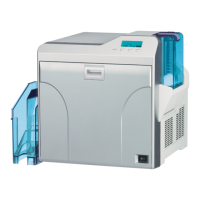
(1) Remove the two screws attaching from the rear side of the
main unit.
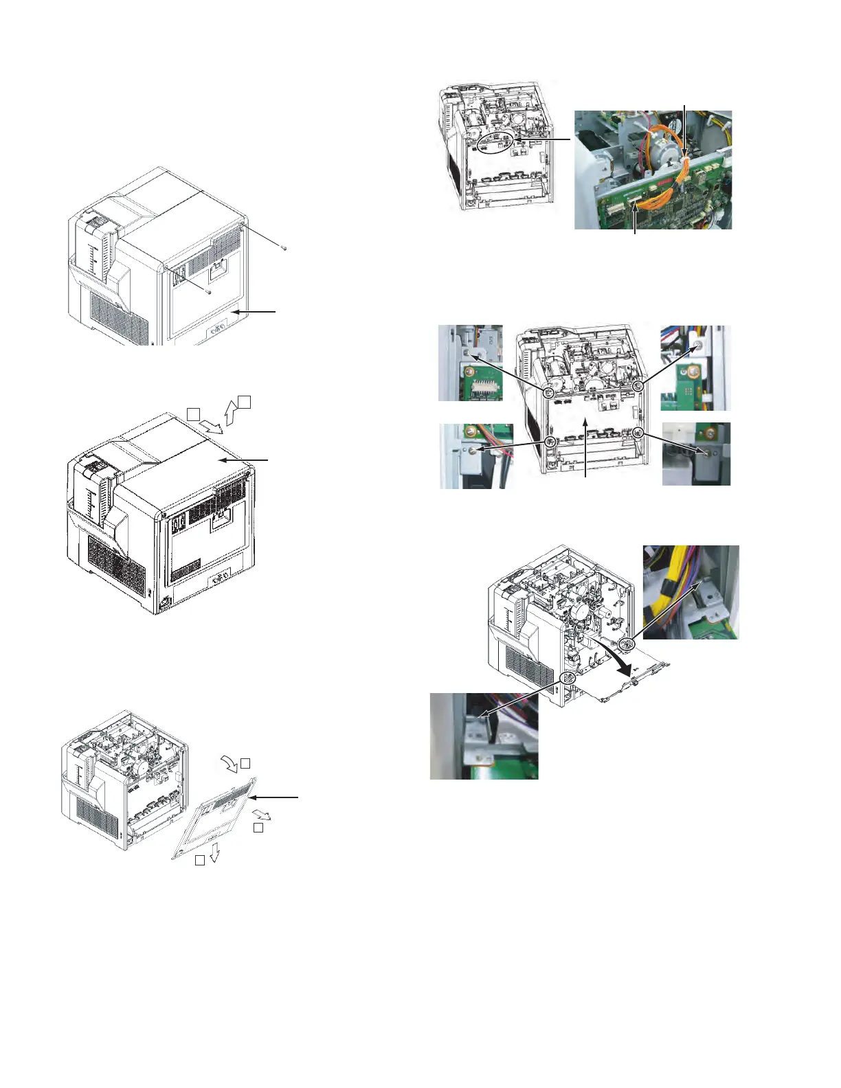
(2) Remove the top cover by sliding it to the direction of the ar-
row.
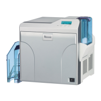
(3) Remove the rear cover by pulling it open to the rear side.
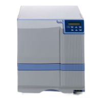
(4) Disconnect the wire connected to the MAIN Board.
(5) Remove the four screws attaching the brackets that fix the
MAIN Board.
(6) Pull open the MAIN Board, and hook the two brackets at
the bottom of the MAIN Board to the frame of the main unit.
• Be careful not to catch wires in between.
Rear cover
Screw:
QYSDSP4012NA x 2
1
2
Slide the top cover to
the rear side about
10 mm, and then pull
it up.
Top cover
1
2
3
1) Swing open the upper part to
the rear side on the axis of the
lower part.
2) Slide the rear cover downwards
to release the hook.
3) Pull the rear cover to the rear side
to remove.
Rear cover
Disconnect the connector from the turn unit.
(Only the models with turn unit)
Release the wires from the wire clamp.
MAIN Board
Screw : QYSDST3006 x 4