6
EN
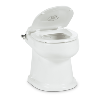
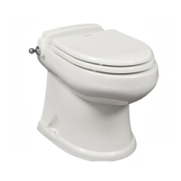
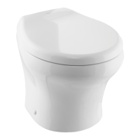
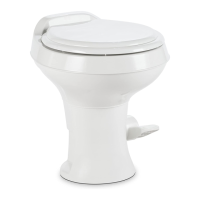
Pre-Installation Full Ceramic Gravity Discharge Toilet
OK TO
FLUSH
DO NOT
FLUSH
C
B
A
VFSHW
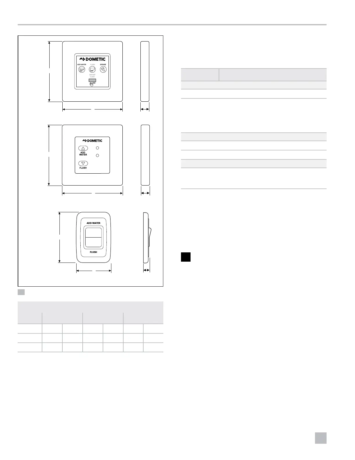
Touch Panel
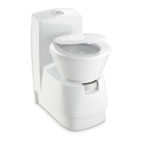
6500 Model
C
C
B
B
A
A
VFS
Flush Switch
6500 Model
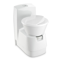
Dometic
Flush Switch
4400 Model
3 Panel and Control Module Dimensions
Measurements
A B C
Model in. mm in. mm in. mm
6500 3.0 77 3.5 89 0.4 11
4400 2.85 73 1.85 47 .63 16
3.3.2 Minimum System Requirements
Dometic recommends that the toilet installation meet the
following minimum requirements:
Component Minimum Requirement
Electrical
Circuit breaker 2 A/12 VDC; 1 amp/24 VDC
Wiring Marine: Refer to ABYC recommendations.
RV: Refer to ANSI/RVIA LV and NFPA 70/
NEC Standards (USA), or CEC I and II
Standards (Canada) for recommended wire
gauge sizes.
Water Supply
Fitting 0.5 in. (13 mm) NPT
Flow rate 2.5 gpm/9.5 lpm minimum at toilet
Discharge
Fitting 4-bolt floor (closet) flange, 3.0 in. (77 mm)
ID, ABS or PVC connection to holding tank,
gravity drain
I
Refer to ANSI 1192 and Z240 RV Series standards,
where applicable, for additional RV toilet
installation guidelines. Specifications are subject to
change without notice.
4 Pre-Installation
WARNING: SHOCK OR FIRE HAZARD.
Use the recommended fuse, circuit breaker, and
wire size. Failure to obey this warning could result
in death or serious injury.
This section has information on the preparation work
required prior to the toilet installation.
4.1 Laying Out the Fresh-Water
System
Figure 4 shows the recommended fresh-water system
layout for the gravity discharge toilets.
I
Use cold water only. Install a shut-off valve in the
water line for maintenance purposes.
 Loading...