7
EN
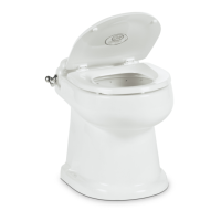
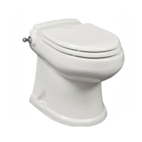
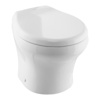
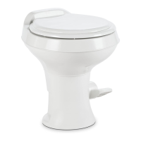
Full Ceramic Gravity Discharge Toilet Installation
q
w
e
r
4 Fresh-Water System Diagram
q
Flush Switch/
Status Panel
e
Gravity Toilet
w
Holding Tank
Status Panel
r
Holding Tank
4.2 Planning the Electrical
Connections
I
Read before proceeding:
• There must be a circuit breaker or fuse for every toilet
control. Make sure the power supply is turned off
during installation.
• For marine applications, follow ABYC guidelines.
• For RV applications, refer to ANSI/RVIA LV and
NFPA70/NEC standards (U.S.A.) or CEC I and II
standards (Canada) for the recommended wire
gauge. Refer to “1.3 Supplemental Directives” on
page 3.
• Use tinned, stranded-copper wire.
• Use crimp-type wire connections. Do not use wire
nuts, as wire nuts can corrode.
Plan all component locations so that the wires are
installed in locations that will always remain dry.
I
Several flush assembly options are available from
Dometic. Follow the instructions included with
each flush assembly.
5 Installation
This section describes how to install the toilets.
5.1 Preparing the Toilet Location
This section describes how to use the toilet templates to
identify and cut the required connection holes.
I
Not all toilet models have templates. Alternative
instructions are provided for the models that do not
have templates. This installation uses through-the-
floor connections.
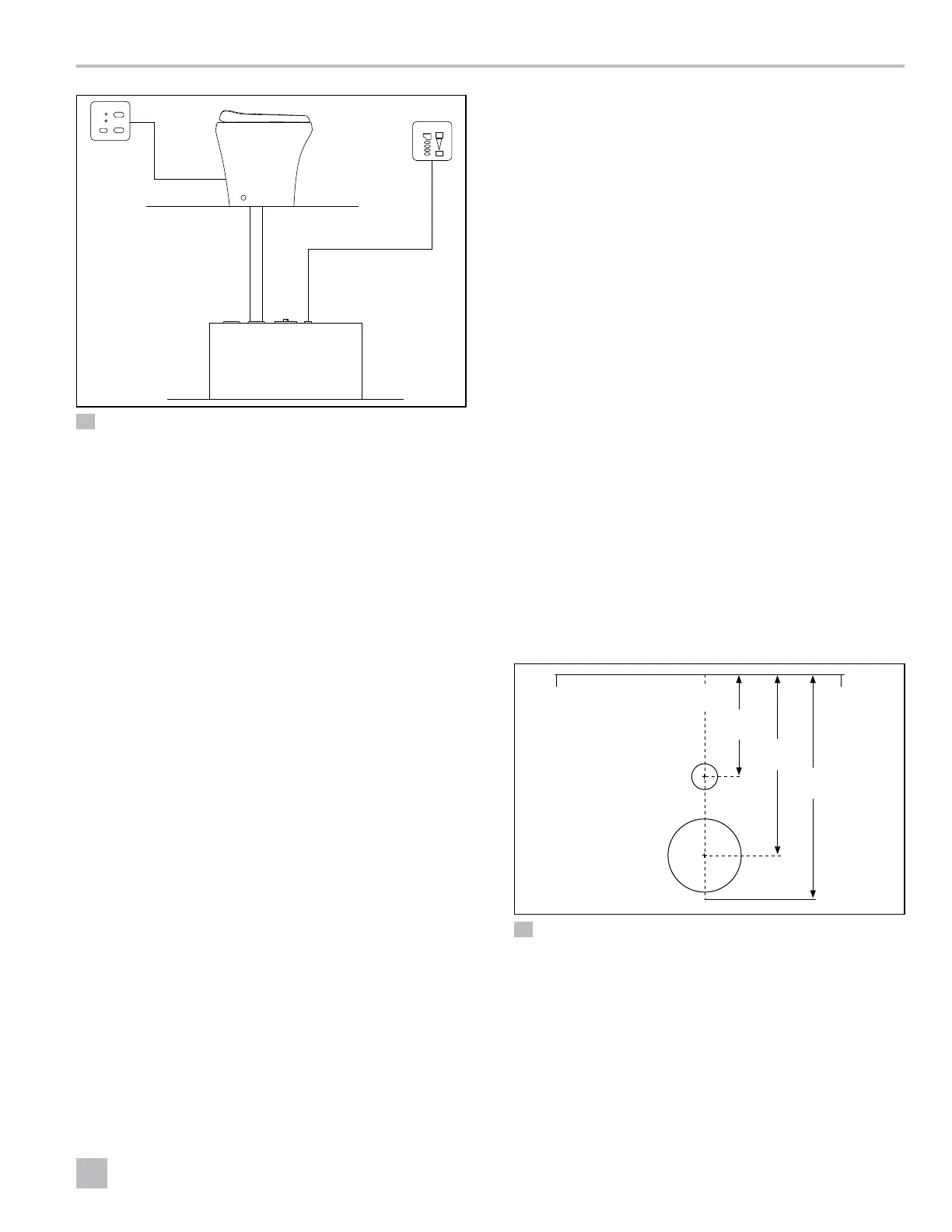
1. Mark the hole locations.
• For 4300 and 4400 series: no template is provided
for these models. Refer to Figure 5 for hole locations.
• For the 6500 series:
– Place the floor-mounting template in the desired
location. Keep at least 11.0 in. (280 mm) between
the centerline of the template and any walls or
interior fixtures. Refer to Figure 6.
– Punch through the center of the holes and floor-
bracket corners in the template.
– Remove the template from the floor.
14 in.
(357 mm)
6 in.
(152 mm)
11.0 in.
(280 mm)
q
w
e
r
t
5 4300 and 4400 Series: Toilet Hole Locations
q
Centerline
e
Rear Corner of Bowl
w
Water Supply Line
& Electrical Wire
Access Hole
r
Discharge Flange
Access Hole
t
Floor
 Loading...