13
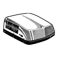
CCC Ducted Installation Instructions
2. Route the previously run AC power supply line through the Romex Connector and into electronic control junction
box.
3. Connect the white to white; black to black; and green to green or bare copper wire using appropriate sized twist wire
connectors. Tape the twist wire connectors to the supply wiring to assure they do not vibrate off.
4. Tighten screws on Romex connector being careful not to pinch and cut into the insulation on power supply leads.
5. Push excess wires into junction box. Install junction box cover. See FIG. 11 and 15B.
B. CONNECTION OF LOW VOLTAGE WIRES
1. Connect the previously run +12 VDC to the red wire labeled +12V protruding from the air conditioner (Do not connect
wires if using the 3308120.XXX Genesis Air Filtration System).
2. Connect the previously run -12 VDC to the black wire labeled -12V protruding from the air conditioner (Do not con-
nect wires if using the 3308120.XXX Genesis Air Filtration System).
3. Connect the two (2) blue wires from the air conditioner to the furnace leads (if applicable). Polarity does not need to
be observed on the furnace leads.
4. Connect the air conditioner yellow wire to the EMS wires (if applicable). Do not allow the yellow wires to short out
or touch, because the compressor will fail to run.
5. Connect the Comfort Control Center
TM
(CCC) cable previously terminated (see Section 6 B. Control Cable) into one
of the control cable leads out of the air conditioner. Either one of the two (2) control cables can be used.
6. Connect the remote temperature sensor lead into the remote sensor extension from the air conditioner (if applicable).
7. Connect the previously terminated (see Section 6. B Control Cable) 4 conductor control cable into one of the control
cable leads out of the air conditioner for the next zone (if applicable).
8. If the unit is a heat pump model, route the ambient air sensor cable, already installed in the base model, through the
grommet in the control kit and attach it to the connector that matches its color (RED P3).
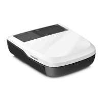
C. COMFORT CONTROL CENTER
TM
INSTALLATION
1. Carefully remove the base plate from the CCC. This may be accomplished by inserting a small screwdriver under
the tab on the bottom edge of the front cover. Gently pry off the cover. See FIG. 12.
2. Insert the control cable through the hole in the base plate and mount the plate to the wall with the two screws pro-
vided. Check the alignment to ensure level installation.
3. Install the previously terminated 4-conductor control cable RJ-11-6C4P connector into the back of the CCC. Gently
press the CCC onto the base plate.
Disconnect the positive (+) 12 VDC terminal
at the supply battery. Damage to equipment
could occur if the 12 VDC is not shut off.
FIG. 12
 Loading...