14
CCC Ducted Installation Instructions
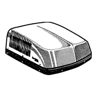
9. INSTALLATION OF AIR CONDITIONER
Installing unit with 3105007.XXX or 3105935.XXX Re-
turn Air Cover
A. INSTALLATION OF CEILING TEMPLATE
2. Remove return air cover and ceiling template from
the 3105007.XXX or 3105935.XXX kit carton.
3. Locate 1/4" mounting bolts.
4. Hold the ceiling template up to the 14-1/4" x 14-1/4"
(±1/8") opening. Be sure the large plate faces the
rear of the RV. See FIG.13A.
5. Start each mounting bolt through the ceiling tem-
plate and up into the unit base pan by hand. Install
wood screw in each end of the ceiling template.
This insures a tight t of the return air cover to
ceiling.
Installing unit with 3105007.XXX or 3105935.XXX Re-
turn Air Cover, continued on page 14, column A.
FIG. 13A
Divider Plate
Ceiling Template
Return Air
Cover
Return Air
Grill
Installing unit with 3308120.XXX Genesis Air Filtra-
tion System.
A. INSTALLATION OF FOAM DIVIDER
1. Check gasket alignment of the air conditioner over
the roof opening and adjust if necessary. Unit may
be moved from below by slightly lifting and sliding.
See FIG. 14A.
2. Locate the foam divider and insert it corner to
corner in the 14-1/4" x 14-1/4" (±1/8") opening
with the adhesive tape up (Do not remove paper
to expose adhesive). The foam divider should be
level with the ceiling (±1/4"). Tear off the excess at
the pre-cut perforations in divider. See FIG. 13B.
3. Peel the paper off of the foam divider and stick it in
place on the center of the rear edge of the return air
opening on the ceiling template See. FIG. 14B.
1. Check gasket alignment of the air conditioner over
the roof opening and adjust if necessary. Unit may
be moved from below by slightly lifting and sliding.
See FIG. 14A.
FIG. 14A
Center Unit From Below
Roof
Gasket
B. INSTALL CEILING TEMPLATE
1. Set dip switches before proceeding (see section 10
on page 17). Position the electrical box towards the
front of the opening with all of the system control
wires connected to the control box except for the
12 VDC power. See FIG. 15B.
Adhesive
FIG. 14B
Foam Divider
Peel Off Paper - Center Divider - Stick To
Rear Flange On Ceiling Template
Installing unit with 3308120.XXX Genesis Air Filtration
System, continued on page 14, column B.
FIG. 15B
Wires Connected To
Control Box
Vehicle
Front
Control
Box
Base
Pan
FIG. 13B
Upside
Down
Foam
Divider
Base Pan
Ceiling
Place Foam Divider In
(14-1/4" x 14-1/4" (±1/8")
Ceiling Opening Against
Base Pan Bottom
Do Not Peel Tape Off
Adhesive
Foam Divider Ceiling
Level (±1/4") Tear
Off Excess
 Loading...