6
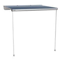
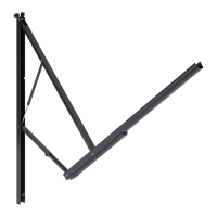
FIG. 5
10° Slope
(Or 9″ Minimum)
Awning Rail
Arm Assembly
5. While holding top arm assembly in place, tighten
adjustable knob to set in place. See (FIG. 3) &
(FIG. 4).
4. PINCH HAZARD. Keep CLEAR
of openings around adjustable pitch arm assem-
bly while adjusting awning pitch (slope). Adjust-
able pitch arm assembly (bottom arm) will tele-
scope. Failure to obey this caution could result
in injury.
Pull top arm assembly (farthest from entry door)
down until awning slopes approximately 10°,
or 9″ minimum from other arm assembly. See
(FIG. 4) & (FIG. 5).
This slope requirement is in addition to the
slope from RV’s awning rail.
SET AWNING POSITION
FEATURES AND ACCESSORIES
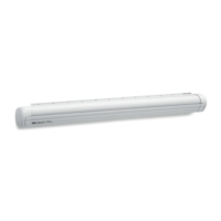
A. Operate Tube LED Light Strip (If
Equipped)
1. Turn tube LED switch to ON position to illumi-
nate tube LED light strip. LED indicator light on
switch plate will illuminate. See (FIG. 1).
Do NOT use tube LED light strip while aw-
ning is closed.
2. Turn tube LED switch to OFF position when tube
LED light strip is not in use. LED indicator on
switch plate will turn off.
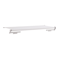
B. Operate Rail LED Light Strip (If Equipped)
Rail LED switch operation and appearance
may vary depending on application.
1. Turn rail LED switch to ON position to illuminate
rail LED light strip.
Rail LED light strip may be used while aw-
ning is open or closed.
2. Turn rail LED switch to OFF position when rail
LED light strip is not in use.
C. Operate Power Channel (If Equipped)
1. Turn power channel switch to ON position to
supply power to tube power channel. Power
channel indicator light on switch plate will illumi-
nate. See (FIG. 1).
Do NOT use tube power channel while
awning is closed.
2. Turn power channel switch to OFF position to
disengage power from tube power channel. LED
indicator on switch plate will turn off.
Attached accessories will NOT function
while switch is in OFF position.
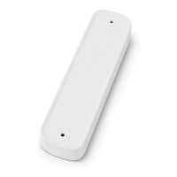
D. Attach Accessories To Power Channel
1. Align power bayonet with power channel slot.
See (FIG. 6).
2. Insert power bayonet fully into power channel
slot, pushing on accessory base (alignment in-
dicator). See (FIG. 6).
FIG. 6
Power
Channel Slot
Alignment Indicator
Power Bayonet
Base Cover
 Loading...