19
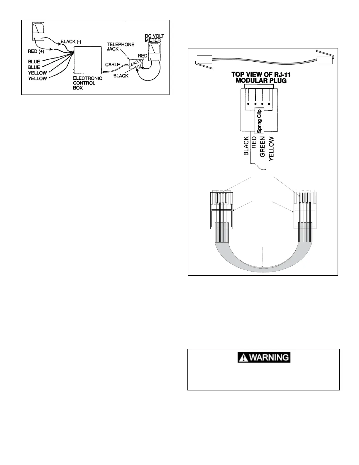
To check DC voltage at the thermostat , remove from
mounting bracket. At the back side of the thermostat
above the RJ-11-6C4P jack are four solder points where
DC input can be checked.
* *------ Negative
Positive--* *
If voltage at control board and control voltage at T-Stat, do
a system RESET on the CCC.
A. Turn the ON/OFF switch to “OFF” position.
B. Simultaneously depress and hold the MODE and
ZONE push-buttons while turning the ON/OFF switch
to “ON”. FF should appear in the LCD display until
the MODE and ZONE push-buttons are released. If
EE appears when the buttons released, do the reset
again. If EE keeps coming back there is a communi-
cation problem with the cable.
C. When a dip switch is turned on or off after initial con-
guration, a system reset will need to be done before
the Comfort Control Center will recognize the updated
selection. Any time a component is added or removed
it would be best to do a reset. There are no repairs to
be done to the Comfort Control Thermostat.
A. DC volts correct at control board and thermostat.
B. No other DC appliances hooked to DC power wires
to the Comfort Control system. (DEDICATED CIR-
CUIT)
C. The DC volts powering the control system could/
may have a strange sine-wave creating erratic op-
eration/behavior. Try a different DC power source
and do a reset and test.
D. Control board, temperature sensors (freeze-re-
mote-ambient UNPLUGGED) test OK.
E. Cable assembly test OK.
F.. Total cable runs not longer than 75 foot total.
G. Conguration correct.
If the following items test OK change the Thermostat.
CABLE ASSEMBLY
A at control cable must be routed from the unit to the
Comfort Control Center. It must be 26 gauge, stranded
copper wire, four (4) conductors (yellow, green, red, and
black). The cable must be terminated with a four (4) posi-
tion telephone RJ-11 or RJ-11-6C4P (preferred) connec-
tor.
Note: Do not use a pre-made telephone extension cable.
The order of the connectors is reversed and will cause a
failure of the system. Both ends of the harness should be
wired the same.
If a telephone extension cable is used it will not light up
the thermostat. Dometic does not provide the cable for
the Comfort Control system. The cable is provided at time
of install. A cable tester available 3107127.007.
CONTROL BOARDS
4.7 Analog Power Module
The Analog Control Box comes in 3 different congura-
tions that are not interchangeable. The Analog Control
Board consists of several relays, plug receptacles and
other components. If any one of these is defective the en-
tire Analog Control Box should be replaced. The Analog
Control Box/Board works with the Analog Thermostat to
change or switch AC circuits that control the operation of
the Duo-Therm Unit.
Air Conditioning
To verify circuits are being completed by the Analog Con-
trol board/box, you would rst disconnect the 6-pin plug
connector from the Analog Control Box. Using a 120 volt
AC incandescent Bulb, check from terminal 5 (white-com-
mon) to the other terminals to determine if a particular
circuit is completed through the Analog Control Box.
Flat Four Conductor Cable
RJ-11-6C4P Connector
Pin 1
Black
Green
Red
Yellow
Black
Green
Red
Yellow
This is an energized circuit. Shock can occur
if not tested properly. Testing is to be done
by a qualied service technician.
 Loading...