29
Up to this point we have mainly covered the discharge
side; however, restrictions of the return air can result in
frost buildup. The Duo-Therm air conditioner requires a
minimum of 40 square inches of FREE AREA. The FREE
AREA – is the opening that remains in a grill or louvered
panel after the restrictions are taken away. For example,
an opening of 10 x 20 inches has 200 square inches.
When this opening is covered with a grill that is 67 per-
cent open, the FREE AREA is (200 x 0.67), 134 square
inches. Dometic return air kits are designed to have the
correct free area; however, some manufacturers use their
own grills. If a manufacturer’s grill is used, it must use the
above formula to make sure the return air is sufcient to
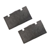
reduce the chances for freeze-up. The lter material must
also be considered as a restriction and subtracted from
the FREE AREA.
11
11
3
3
3
1/2
1/2
1/2
1/2
81
121
EXAMPLE OF HOW TO DETERMINE
FREE AREA OR % OPEN AREA:
TOTAL AREA = 11 X 11 = 121
FREE AREA = 3 X 3 X 9 openings
= 81
% OPEN AREA = = 67%
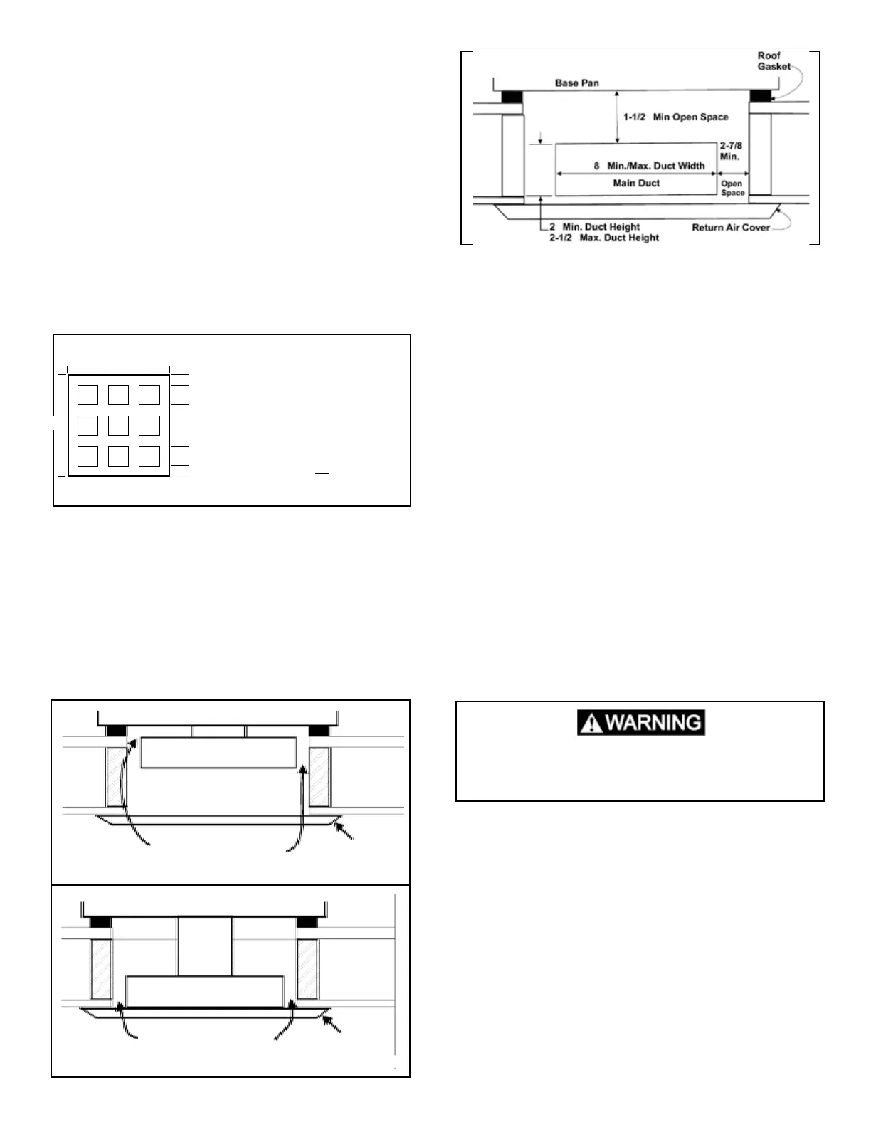
Main ducts running through the 14-1/4″ x 14-1/4″ (±1/8″)
opening must leave space between the duct and return
air grill or duct and bottom of the air conditioner. The gap
between the top of the main duct to the bottom of the air
conditioner should be a minimum of 1-1/2″. If the return
air is ducted into the 14-1/4″ x 1/4″ (±1/8″) opening, the
system must equal the 40 sq. inches of free air required
by the air conditioner. Grills or registers used in this duct
must be equal to or greater than the duct in square inch-
es.
5.4 Air Distribution Box (ADB)
Improperly installed, the air box can be a source of cool-
ing problems. The air box must be sealed to the ceiling
template to prevent the mixing of discharge and return air.
Cold discharge air that enters into the return air portion
of the air box can cause a false temperature reading at
the thermostat and shut down the compressor. This will
cause short cycling and or frost formation on the inside
coil. In some instances, the ceiling template is bent when
the anchor bolts are over tightened, causing gaps be-
tween the air box and the ceiling template. These gaps
can be sealed with aluminum tape or a closed cell foam
weather strip. The duct connecting the air conditioner or
heat pump must be air tight. Use aluminum tape to seal
the joints. The thermostat sensing bulb must be properly
located to control temperature. If the sensing bulb is left
curled against the side of the electric box or used as a
ground connection, improper operation will occur. Relo-
cate the sensing bulb in its proper place as indicated in
the Installation and Operating Instructions. Make sure you
have the correct discharge duct for the thickness of the
roof. Make sure the discharge louvers are not restricted
and lter clean.
Section 6
The Comfort Control Center conguration relates to set-
ting the Dip switches and particular components (remote
temperature sensor, cold [freeze] control and ambient
sensor) that can be plugged into the AC power module
board according to the type of unit and accessories in-
cluded.
Note: If the conguration of the Dip switches and plug-in
components are not correct, the air conditioner or heat
pump could operate erratically or not operate at all.
Conguration should be done at the time of installation
by the installer. To check the conguration, rst locate
the Electronic Control Kit or main power module on roof-
mounted units. Next remove any cover or covers for ac-
cess to Dip switches and Sensor Plugs (P3, P4 and P5).
Both are located on the AC Power Module Board. All Dip
switches are in the “OFF” position at the time of manufac-
Conguration Comfort Control
This is an energized circuit. Shock can occur
if not tested properly. Testing is to be done
by a qualied service technician.
BASE PAN OF AC
MAIN DUCT
SPACE LEFT OPEN
FOR RETURN AIR
RETURN
AIR GRILL
RETURN
AIR GRILL
MAIN DUCT
SPACE LEFT OPEN
FOR RETURN AIR
BASE PAN OF AC
″
″
″
″
″
 Loading...