20
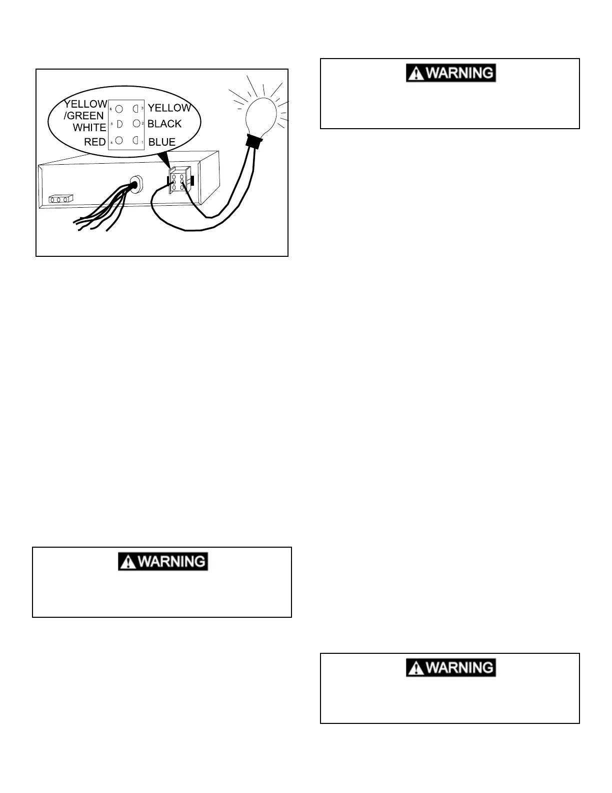
When the thermostat calls for that function and the Circuit
is completed the light will illuminate.
Terminal
1. Is a blue wire and the compressor circuit.
2. Is a black wire and the High Fan circuit.
3. Is a yellow wire and not used.
4. Is a red wire and the Low Fan circuit.
5. Is a white wire and the common AC connection.
6. Is a green/yellow wire and chassis ground.
If the compressor is not coming on disconnect the cold
control and try again.
Note: DO NOT use a voltmeter to do these checks as it
will give erroneous readings.
If the circuit is completed (light illuminating) and a com-
ponent is not operating, the problem is in the rooftop unit/
wire harness.
Furnace
To verify circuits are being complete by the Analog control
board/box, slide System Switch to Furnace and slide the
Temperature Set Lever to maximum temperature level.
There should be continuity thru the two blue/white wires
at the control board/box. Before condemning the control
board/box, verify DC voltage, t-stat and cable OK.
Controlling the compressor and fan speeds same as be-
fore. To verify heat strip operation disconnect the 3- pin
plug on the control and using a 120 volt AC Bulb, check
from terminal 1 to terminal 3 (white-common). If the circuit
is completed the bulb will illuminate.
Note: DO NOT use a voltmeter to do these checks as it
will give erroneous readings.
If the circuit is completed and a component is not operat-
ing, the problem is in the heat strip.
To verify circuits are being completed by the Analog con-
trol board/box, you would rst disconnect the 6-pin plug
connector from the Analog Control Box. Using a 115 volt
AC incandescent bulb, check from terminal 5 (white-com-
mon) to the other terminals to determine if a particular
circuit is completed through the Analog Control Box. If the
circuit is completed, the light will illuminate.
Terminal
1. Is a blue wire and the compressor circuit.
2. Is a black wire and the High Fan circuit.
3. Is a yellow wire and reversing valve circuit.
4. Is a red wire and the Low Fan circuit.
5. Is a white wire and the common AC connection.
6. Is a green/yellow wire and chassis ground.
Note: DO NOT use a voltmeter to do these checks as it
will give erroneous readings. If the circuit is completed
(light bulb coming on) and a component is not operating,
the problem is in the rooftop unit/wire harness.
4.8 COMFORT CONTROL MAIN POWER
MODULE
Note: The 5 button thermostat will only work with the
control board that has 8 dip switches. The 4 button
thermostat will only work with the control board that
has 5 dip switches. The two different systems are not
compatible.
The AC power module board consists of a relay, dip
switches, plug receptacles and other electrical compo-
nents. If any one of these are defective the complete AC
Control Box (some models only AC power module) must
be replaced. The 3 amp fuse is the only replaceable part
on the module board. The board receives messages from
the Comfort Control Center, and completes AC circuits to
operate the unit. Before diagnosing the AC power module,
make sure the Conguration, Cable assembly, Remote
Sensor, Freeze Control, Ambient Sensor, DC/AC voltages
and operation has been checked and is correct.
This is an energized circuit. Shock can occur
if not tested properly. Testing is to be done
by a qualied service technician.
Air Conditioners with Heat Strip
This is an energized circuit. Shock can occur
if not tested properly. Testing is to be done
by a qualied service technician.
Roof Top Heat Pump
This is an energized circuit. Shock can occur
if not tested properly. Testing is to be done
by a qualied service technician.
3
6
2
1
5
4
 Loading...