Technical description MSI924M
12
I
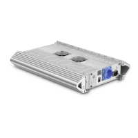
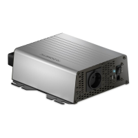
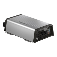
7.1 Control elements
The inverter has the following connections, displays and control elements on the
back:
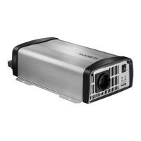
The inverter has the following connections, displays and control elements on the
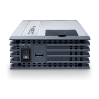
front:
NOTE
The individual values are found in the chapter “Technical data” on
page 22.
No. in
fig. 4,
page 4
Designation Description
1 Terminal Setup operation via remote control
2 RS-232 port,
REMOTE port
Connection of a PC using a serial RS-232 interface or
connection of the MCR9M remote control
3 POS+ Positive terminal
4 NEG– Negative terminal
5 Earth terminal Earthing on the vehicle bodywork, not needed for
truck installation
No. in
fig. 5,
page 4
Designation Description
1 Main switch
“ON/OFF/REMOTE”
switch:
Switches the device on, off or to operation via the
remote control (accessory)
2 “Input Level” LED Displays the input voltage range
3 “Load Level” LED Displays the power being supplied
4 Dip switch Makes settings on the inverter (such as mains voltage,
mains frequency, energy-saving mode).
5 Safety socket 220 V output
MSI924M-IO-16s.book Seite 12 Mittwoch, 5. April 2017 5:18 17
 Loading...