Description of the Controls Q3 & Qht Controls for Chilled Water Systems Operations Manual
2 L-2962 ENGLISH
DESCRIPTION OF THE CONTROLS
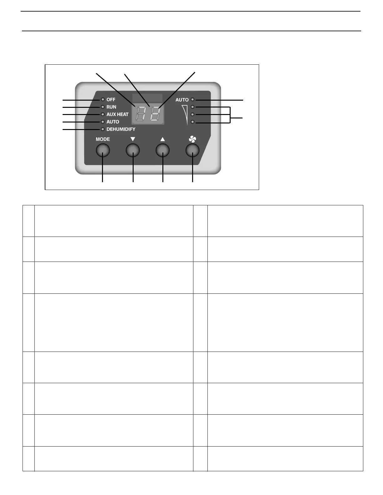
Figure 1: Q3 Diagram - Control Display Panel and Indicators
Table 1: Q3 Diagram Description of Control Display Panel and Indicators
1
Data Display - Large LED readout displays current
temperature, set point, programmed values and error messages.
9
AUTO Mode Indicator - Lights when Auto Mode is selected.
Auto Mode can only be selected if the optional Aux Heat
function is enabled (see Programmable Function “12: Aux Heat
Enabled/Disabled” on page 9).
2
AUTO Fan Mode Indicator - Lights when fan is running in
Automatic Fan Mode.
10
AUX HEAT Indicator - Lights when the optional Aux Heat
Mode is selected. Aux Heat may only be selected if the optional
Aux Heat Programmable Function 12 is enabled.
3
Fan Speed Indicators - Column of three LEDs that indicate
the current fan speed of high, medium, or low (refer to fan speed
operation).
11
RUN Indicator - Lights when the Run Mode is selected. The
Run Mode will automatically switch from Cool to Heat
depending on the set point, cabin temperature, and entering
loop water temperature.
4
FAN Button - Press to select Automatic or Manual Fan Mode,
indicated by the AUTO Fan LED indicator being on or off. In
Manual Fan Mode, additional presses of the Fan button will
adjust fan speed higher, then lower, then back to AUTO. In
AUTO Fan, fan speed is controlled by the control board as a
function of the difference between set point and inside
temperature. See Programmable Function “3: Fan Response
Differential” on page 8.
12
OFF Mode Indicator - Lights when system is off. Note that
the Data Display remains on. You can continue to adjust set
point, display temperature readings and activate the manual
fan to circulate air while the system is in the Off Mode.
5
UP Button - Press to adjust set point up. In programming mode
press to scroll through program modes and adjust values.
13
Cooling Indicator - A dot in the upper left corner of the data
display lights to indicate the bypass valve is open in COOL
mode. In AUTO mode, the COOL LED indicator lights to
indicate the bypass valve is open.
6
DOWN Button - Press to adjust set point down. In
programming mode press to scroll through program modes and
adjust values.
14
Heating Indicator - A dot in the upper left corner of the data
display lights to indicate the bypass valve is open in HEAT
mode. In AUTO mode, the HEAT LED indicator lights to
indicate the bypass valve is open.
7
MODE Button - Press to cycle through the modes of operation
(refer to indicators). Mode sequence selections are OFF, RUN,
AUX HEAT (optional), AUTO (RUN with optional AUX HEAT),
and DEHUMIDIFY.
15
Set Point Indicator - A dot in the upper center of the display
lights to indicate the set point is being adjusted. Normally
display defaults to inside temperature.
8
DEHUMIDIFY Mode Indicator - Lights when the Dehumidify
Mode is selected. Flashes if optional humidity sensor is
connected and operating in Cooling Mode.
16
Manual Fan Mode Indicator - AUTO Fan indicator turns off
when fan is running in Manual Fan Mode.
4
1
2
765
8
9
11
12
13,14 15,16
10
3