- 16 -
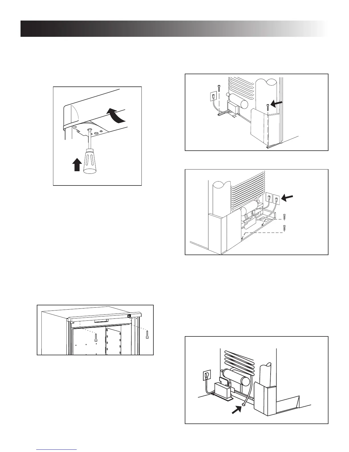
3. ONE SCREW INSTALLED IN THE REAR BASE.
OPTIONAL SCREW MAY BE ADDED.
RM2451, RM2454, RM2551, RM2554, DM2652,
DM2662, DM2663, DM2852, DM2862, RM3762,
RM3962 & NDM1062
RM1350 & NDA1402
DRAIN WATER HOSE
• Hose must not contact the boiler casing.
• Hose must not be kinked.
• Hose must not be routed uphill at any point.
• Perforated plug must be present at end of hose.
OPTION 1 - THROUGH FLOOR
Drill hole through ooring, see FIG 16. Seal around hole.
Check to make sure the supplied hose is long enough – if not,
installer will have to supply extra length of hose.
Ice Maker
Cord
(optional)
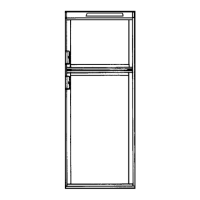
2. TWO SCREWS INSTALLED IN THE TOP
FRAME.
RM2451, RM2454, RM2551, RM2554, DM2652,
DM2662, DM2663, DM2852, DM2862 & NDM1062
a) Gently push the tabs out of the hole in the hinge
with a at blade screwdriver (both sides).
b) Carefully tilt the top decoration panel and lift to
remove from top frame. Be careful not to dam-
age the circuit board and wires.
c) Install the two screws in the top frame, the holes
are accessible from underneath.
d) Seal the opening for the screws with aluminum
tape.
e) Replace the top decoration panel. Be careful not
to pinch the wires behind the panel. Make sure
the tabs snap back into the holes in the hinge
plate.
RM3762, RM3962, RM1350 & NDA1402
Fasten the refrigerator with two screws through the
holes underneath the top decoration panel.
Hole for drain
water hose
Boiler
casing
Hose
INSTALLATION PROCEDURE
2
1
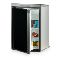
General view. Features may vary by model.
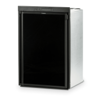
General view. Features may vary by model.
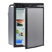
General view. Features may vary by model.
Optional
Screw
FIG 16 - DRAIN WATER HOSE
 Loading...