Installation, Operation and Maintenance manual
32
Downflo
®
Evolution
Bursting panel indicator switch
According VDI, each bursting panel may be combined with signalling devices which
will trigger a shut down or a controlling mode. Therefore Donaldson Torit will supply
a bursting disc indicator switch with each bursting disc (see scope of delivery).
When connecting the indicator switch, the following must be taken into account:
• maximum supply voltage : 30 Volt DC
• maximum current : 100 mA / 3 Watt
When the indicator is located in a hazardous area, the electrical circuit to the indicator
must be intrinsically safe. (an optional isolation amplifier is a perfect solution)
As the burst indicator is a very sensitive device, it is recommended to use
always a isolation amplifier, this gives the best guarantee for TROUBLE FREE
electrical functioning of the indicator.
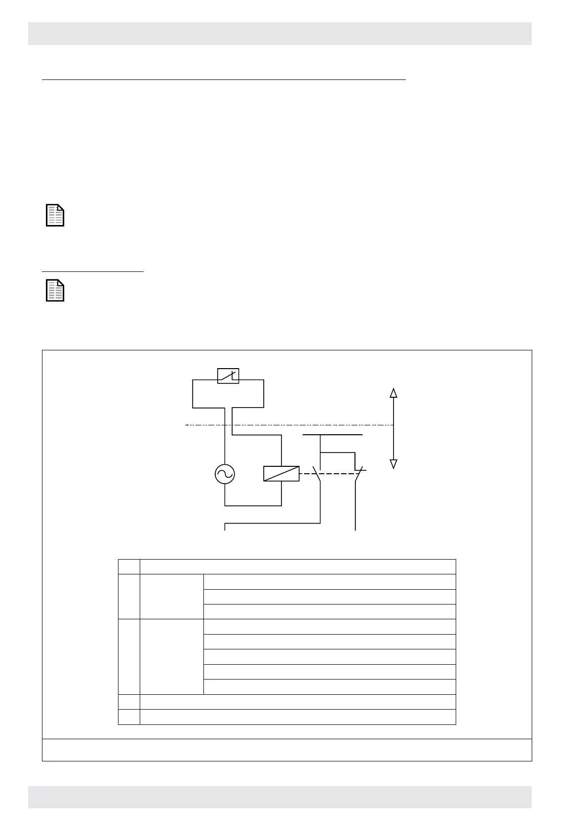
Typical wiring diagrams
These diagrams are only for information as the wiring diagram will be different
for each individual dust collector installation (depending on the configuration of
the dust collector; availability of dust release system, damper valve actuator,
alarm, fan, etc. and requirements of the customer).
1
5
4
3
R1
2
24VAC
(24VDC)
L:230V
1 burst indicator
2 disconnect: fan set
dust relase system (rotary airlock, screw conveyor, etc)
power supply to printed circuit board (pulse cleaning)
3 engage: alarm
lamp
horn
signal to central fire dispatching
damper valve actuator (if required)
4 customer delivery
5 Donaldson delivery
Figure 22: Typical wiring diagram - non-hazardous area