10
Only related for devices with call button(s):
4 PIN (SWITCH)
Use the yellow cable to connect the button to the IP Video Door Station.
NOTICE
Please take care when connecting the cables and wires. Connecting the cables and wires the wrong
way may damage the device. Wires without insolation material must not protrude out of the green
screw connection terminal, it may lead to electrical short and damage the device.
PORT DESCRIPTION
LAN/POE RJ45 jack to connect a standard Network cable Cat.5 or better, coming from the Internet
Router/PoE-Switch/PoE-Injector.
NOTICE
Do not power the device simultaneously via the power supply from the power
supply unit (mains adaptor) and the power supply via PoE.
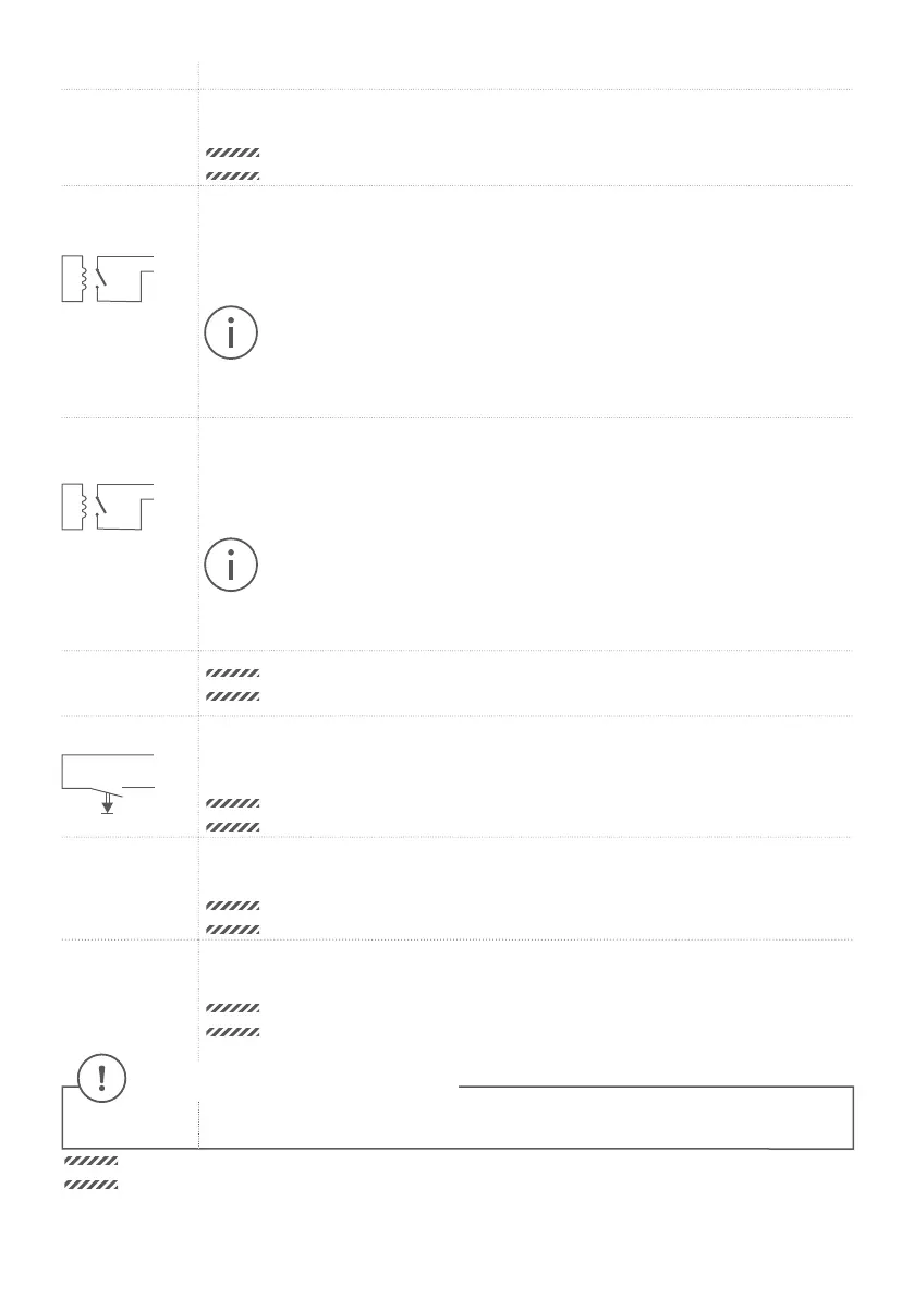
REL1, REL1
REL1
REL1
Bi-stable latching relay #1, max. 24 V DC/AC, 1 Ampere. Security feature: The relay keeps
its state even in the case of loss of power. You can configure the default state of the relay
(open/close) via the DoorBird App. These ports can be used to connect e.g. an electric door
opener. The device does not supply power to the connected device. The power supply for
the electric door opener must be installed separately.
When wiring an electric door opener directly to a door station, there is a risk that
the electric door opener could be tampered by unauthorized third parties (e. g. by
breaking the door station and short-circuiting the wiring of the door opener).
Therefore, we generally recommend the use of a remote safety relay mounted
indoors (e. g. DoorBird I/O Door Controller A1081) for wiring an electric door
opener for a more secure installation in your home.
REL2, REL2
REL2
REL2
Bi-stable latching relay #2, max. 24 V DC/AC, 1 Ampere. Security feature: The relay keeps
its state even in the case of loss of power. You can configure the default state of the relay
(open/close) via the DoorBird App. These ports can be used to connect e.g. an electric door
opener. The device does not supply power to the connected device. The power supply for
the electric door opener must be installed separately.
When wiring an electric door opener directly to a door station, there is a risk that
the electric door opener could be tampered by unauthorized third parties (e. g. by
breaking the door station and short-circuiting the wiring of the door opener).
Therefore, we generally recommend the use of a remote safety relay mounted
indoors (e. g. DoorBird I/O Door Controller A1081) for wiring an electric door
opener for a more secure installation in your home.
BELL, BELL
NOTICE
Reserved – Do not use!
EXT, EXT
EXT
EXT
Door opener button, max. 0 V DC/AC, 0 Ampere. These ports can be used to connect e.g.
a door opener button inside the home. It will trigger the first bi-stable latching relay of the
device (REL1, REL1).
NOTICE
Please make sure to add no voltage on these ports. Extra voltage may destroy
the device immediately.
15 VDC - 15 V DC Power supply input, negative pole (-). Please connect the black wire of the DoorBird
power supply unit (mains adaptor) here, if you do not power the device using PoE.
NOTICE
Do not power the device simultaneously via the power supply from the power
supply unit (mains adaptor) and the power supply via PoE.
15 VDC + 15 V DC Power supply input, positive pole (+). Please connect the red wire of the DoorBird
power supply unit (mains adaptor) here, if you do not power the device using PoE.
NOTICE
Do not power the device simultaneously via the power supply from the power
supply unit (mains adaptor) and the power supply via PoE.
 Loading...