6006-065-B-3-20
9
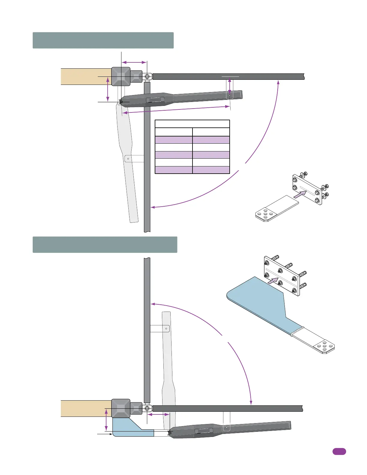
Weld directly
to support post
OR to steel plate
Weld directly
to support post
OR to steel plate
Reinforcing steel plate
for sleeve anchors
if desired.
(Not Supplied)
90° Layout “PULL to Open”
90° Layout “PUSH to Open”
Weld front and rear brackets
directly to gate and metal
support post if desired.
If mounting brackets with
bolts to the gate and wall,
weld reinforcing steel plates
to the brackets. Fully weld
around entire brackets.
Note: The ideal installation measurements are
A = 7-3/4” (19.7 cm) and B = 8-1/2” (21.6 cm).
If different measurements are used, the sum of
A and B cannot be greater than 18” (45.7 cm).
6 1/2” (16.5 cm)
35 1/2” (90.1 cm)
Open Gate
A
B
Closed Gate
7 3/4” (19.7 cm) Ideal
8 1/2”
(21.6 cm) Ideal
7 3/4” (19.7 cm)
8 1/2” (21.6 cm)
9” (22.9 cm)
9” (22.9 cm)
7 1/2” (19.1 cm)
8 1/2” (21.6 cm)
7 3/4” (19.7 cm)
9 (22.9 cm)
8 1/2” (21.6 cm)
7 1/2” (19.1 cm)
Options
AB
90°
Closed Gate
Open Gate
8 1/2” (21.5 cm)
7 3/4”
(19.6 cm)
90°
Addition to rear bracket must
be fabricated to reach post/wall.
Fabricated
Reinforced
Steel
Pla
te
(Not Supplied)
Reinforcing
steel plate for bolts
if desired. (Not Supplied)
Rear
Bracket
(Su
pplied
)
A rear bracket will need to be fabricated.
The bracket will vary in size depending on
the gate hinge inset. It can be attached to
the wall by welding or bolting, depending
on the type support post/wall.
The bracket MUST be level and VERY
secure to the wall. Extreme force will
be exerted on this bracket during gate
cycling.