9150-065-V-12-12
22
ON
ON
REVERSE
SENSITIVITY
REVERSE
LOOP
EXIT
LOOP
KEY SWITCH
DOORKING
4602-010
SW1 SW2
OPEN
TIMER
NC
1
2
3
4
5
NO
18
17
16
15
14
13
12
11
10
9
8
7
6
5
4
3
2
1
9410
9409
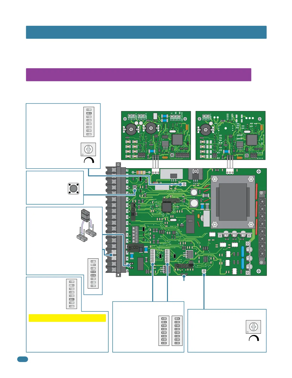
3.1 4602 Circuit Board Description and Adjustments
SECTION 3 - ADJUSTMENTS
The switch settings and adjustments in this chapter should be made after your installation and wiring to the operator(s) is
complete. Whenever any of the programming switches on the circuit board are changed, power must be shut-off, and then
turned back on for the new setting to take effect. Every time the 9150 is powered up, the First open command will automati-
cally run “Multiple gate cycles” that will locate and remember the gate’s open and close positions (See page 25).
Auto-close timer (when
turned on) SW 1, switch 2.
Adjust from 1 second
(full counter clockwise) to
approximately 23 seconds
(full clockwise).
Dry relay contacts
(terminals 15-16) can be
set for Normally Open
(NO) or Normally Closed
(NC) operation by placing
the relay shorting bar on the
N.O. or N.C. pins respectively.
SW 1, switches 4 and 5 must
be set to control relay. See
next page for descriptions.
123
Auto-Close Timer
Dual Channel Loop Detector Single Channel Loop Detector
Dry Relay Contact
NC
NO
Set the DIP-switches
on the circuit board
to the desired
setting. See switch
setting charts on
next 2 pages.
DIP-Switches
ON
12345678
SW 2
ON
12345678
SW 1
ON
1 2 345678
SW 1
Cycles the operator
when pressed. Gate
opens to full open
position ONLY.
Surface Mounted LEDs Indicates that low voltage power is applied to the circuit board.
Input LEDs should be OFF and will only illuminate when the input is activated. Pulse LEDs will
blink as the operator is running. They can be either ON or OFF when the operator is stopped.
Key Switch
Adjust reversing sensitivity.
Full counter clockwise for
minimum sensitivity, full
clockwise for maximum
sensitivity. See page 26.
Min Max
Sensitivity
Inherent Reverse Sensor
Self-test (when
turned on) SW 1,
switch 6.
CAUTION
Do not run self-test with the operator
connected to the gate. The drive chain
must be disconnected before running
the self-test. This feature is designed
for bench testing ONLY.
Self-Test
ON
123456 78
SW 1
UL 325
Terminal
Power LED
Pulse LEDs
Input LEDs
Magnetic
Sensors
See page 26.
ON
12345678
SW 1
Typical Settings
Exit Loop Port Reverse Loop Port
See page 30.See page 34.

 Loading...


