9150-065-V-12-12
10
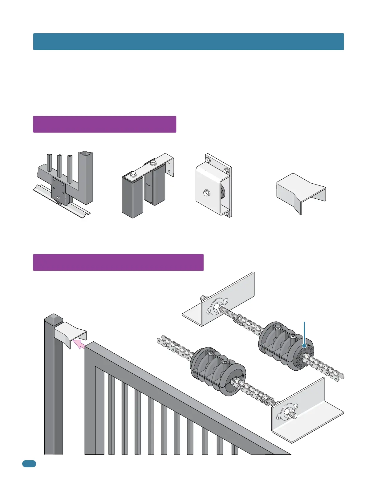
Gate End Retainer
End
Post
SECTION 1 - INSTALLATION
1.2 Physical Stops for the Gate
1.1 Hardware for the Gate
Good hardware is essential for proper operation of a sliding gate. DoorKing has a full line of gate hardware products that will
ensure safe, reliable and long lasting gate operation. The gate must be properly installed and roll smoothly in both directions.
Rubber bumper faces toward
operator. it will make contact
with the operator housing
during the initial automatic
“Multiple gate cycling” to
set the open and close
gate position.
The 9150’s automatic open/close gate limits must have a physical
stop on the open and close positions of the gate. This can be the
use of end posts with gate end retainers or chain stops, depending
on the mounting position of the operator. Note: Chain stops DO
NOT meet the ASTM F2200 requirements for physical gate stops.
Gate End Retainer - Helps stabilize
the end of the gate in the open or
closed position. Recommended for
all slide gate applications.
Endless Idler Assembly with
Protective Cover - Helps to
minimize a pinch point for a
180° chain return.
Guide Rollers with
Protective Covers - Helps
to minimize a pinch point
on the gate.
Roller Bearing V-Wheels
with Protective Cover - Helps
to minimize a pinch point on
the gate’s wheel and V-rail.
Chain Stops
Gate
Prior to beginning the installation of the slide gate operator, we suggest that you become familiar with the
instructions, illustrations, and wiring guide-lines in this manual. This will help insure that your installation is
performed in an efficient and professional manner compliant with UL 325 safety and ASTM F2200 construction
standards.
The proper installation of the vehicular slide gate operator is an extremely important and integral part of the
overall access control system.
Check all local building ordinances and building codes prior to installing
this operator. Be sure your installation is in compliance with local codes.

 Loading...


