DL06K Interim Tire-4 Diesel Engine Disassembly and Reassembly of Major Components
101
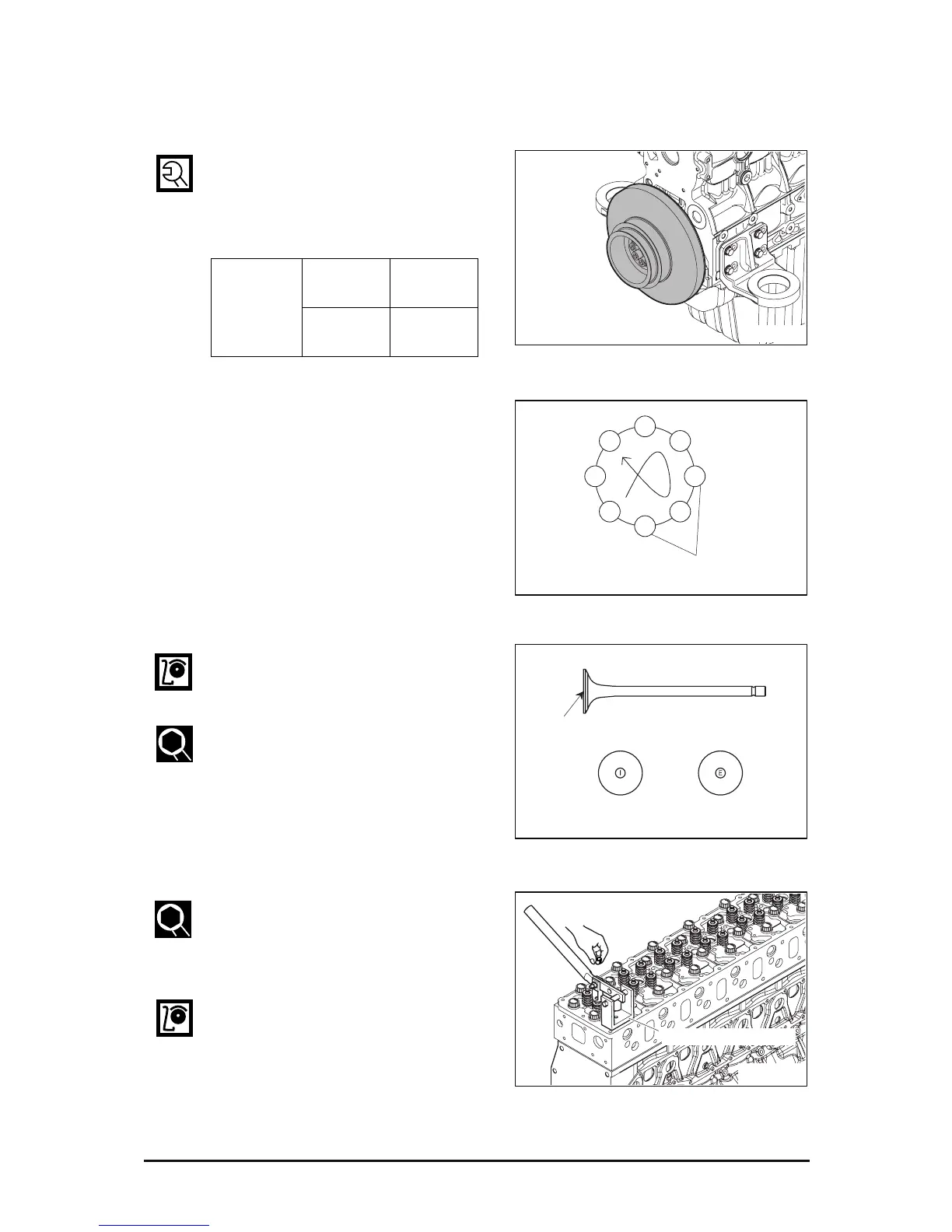
3.3.17. Crankshaft pulley and vibration damper
z Mount the vibration damper on the
crankshaft pulley, and fasten fixing
bolts in fastening order with the
predefined torque.
3.3.18. Intake and exhaust valve
z Check the "I" and "E" mark on the
valve head, before assembling the
valve to the cylinder head.
z Assemble the valve stem seal to the
valve guide, using the valve stem seal
assembly jig.
z Item number of the valve stem seal
assembly jig : EF.121-253
z Assemble the valve cotter by pressing
the retainer, using the valve spring
compression jig, after installing the
valve spring and retainer.
z Item number of the valve spring
compression tool : EF.123-065
z Check whether the valve is assembled
correctly, by beating the valve stem
softly, using the rubber hammer.
Torque
Vibration
damper
6.2 kgf•m
Crankshaft
pulley
20 kgf•m
EK4OM051
EE1OM155
1
6
4
7
2
5
3
8
Bolt tightening order
EE1OM156
Valve marking position
Intake valve Exhaust valve
EG9OM078
Valve spring compression jig
 Loading...