- 27 -
When the System is Not Working
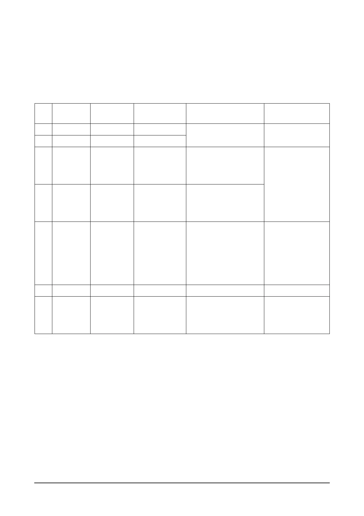
In the event that the engine governor system is not working properly, you can deduce the cause by performing
the test in the following chart.
Here, (+) and (-) represent the polarities of the measuring instrument. Using the method in the chart below, if
the test results are normal, there may be a problem in the actuator or the actuator wiring connections so the
actuator must be inspected.
Step
Measured
terminals
Time of
measurement
Normal value Presumed cause of fault Troubleshooting
1 F (+) & E (-) E/G stopped DC 24V
Battery failure
Faulty connection
Check battery line,
replace battery.
2 F (+) & E (-) E/G starting DC 15 or higher
3 C & D E/G stopped
300 ~ 1,200
using test ohm-
meter
Defective speed sensor
Damaged or incorrectly
connected speed sensor
wiring
Check sensor line.
Replace speed sen-
sor.
4 C & D E/G starting
1.5V or higher
when measured
with tester AC
voltmeter
Gap between speed sen-
sor and ring gear too wide.
Defective speed sensor
5 A & B E/G stopped
3.8 ~ 4.5
using test ohm-
meter
Check line for short circuit
if measured value is less
than 3.8
Check line for open circuit
if measured value is over
4.8
Defective actuator
Check actuator line for
short or open circuit.
Replace actuator
6 P (+) & G (-) Key S/W ON DC 9.5 ~ 10.5V Faulty control device Replace controller.
7 F (+) & A (-)
While in
operation
DC 9 ~ 15V
when normal
DC 1 ~ 3V when
abnormal
Low speed setting.
Short or open circuit in
actuator wiring connection
Actuator
Check speed settings.
Check actuator line.
Check actuator and
replace if faulty.
 Loading...