- 34 -
Installation
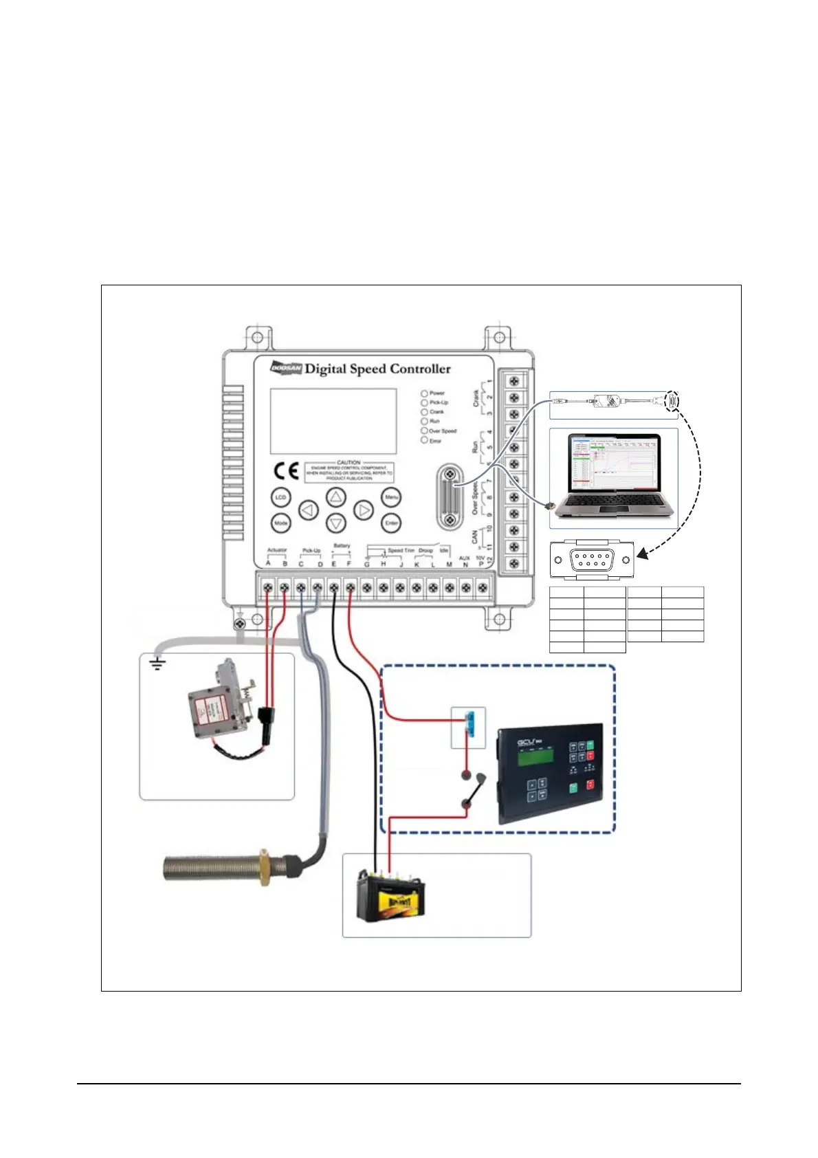
Digital Speed Controller should be connected to the pick-up sensor attached on the engine and the actuator.
Speed trim, droop, idle and aux terminals can be used for additional functions in connection with surrounding
circuits. Contact points a or b can also be used to operate external devices using crank, run and over speed
functions. RS232 and CAN port allow communication with PCs or external host computers for data transfer
and monitoring functions.
1. Connecting to the engine
(1) Battery, pick-up and actuator connection diagram
Shield Cable
Governor Actuator
Magnetic Speed Pick-Up
Battery
DC +24 V
Generator Control Unit
Fuse
+24 V/15A
MC
EEX190003
Toolkit Cable
RS232
1
Pin No.
Description
Pin No.
Description
2
3
4
5
-
-
-
-
GND
6 +3.3V
/MCLR
PGC2
PGD2
7
8
9
54321
9876
 Loading...