- 38 -
3. Connecting to crank, run, over speed and communication
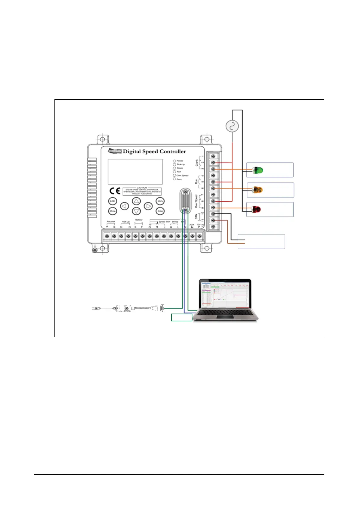
(1) Crank, run, over speed and communication connection diagram
It is used to deliver operation information to external devices by activating contact point (a or b) when activat-
ing crank, run or over speed functions.
RS232 and CAN communication is connected to external PCs or hosts so that the controller can
transmit system settings or operation information.
(2) Connecting to crank terminals
Terminals 1, 2 and 3 are the ones for crank output contact point and the contact point will be in opera-
tion when the controller activates the crank function. The second crank contact point is a shared termi-
nal while terminals 1 and 2 are for the contact point b and terminals 2 and 3 for the contact point a.
Contact points a and b start to operate when the controller reaches at the RPM delivering control sig-
nals to the actuator after the engine is activated. The diagram shows wiring to operate AC220V lamp.
The shared terminal is for 220V inputs and the crank lamp turns on when the contact point a starts to
operate.
RS232
CANL
CANH
CAN
Crank
Lamp
AC220V
N
L
Run
Lamp
Over Speed
Lamp
Node
EDL11160008
Toolkit Cable
 Loading...